Table of Contents
Introduction
In the Asterfusion 2025 Q4 update for the new campus Enterprise SONiC Distribution AsterNOS-V5.2R015, we have introduced a new feature: PIM Dynamic RP. This ties in with the previous article on PIM Sparse Mode, providing a clearer understanding of PIM Sparse Mode.

In this article, we will briefly review what RP is, how the BSR protocol, which PIM Dynamic RP relies on, helps elect the RP in a PIM network, and how to configure PIM Dynamic RP on Asterfusion.
What are RP and DR?
In PIM Sparse Mode, without considering the SPT switchover, we encounter a scenario where:
- From the multicast source to the RP, there is a source tree (S,G), and
- From the RP to downstream receivers, there is a shared tree (*,G).
As we can see, the RP (Rendezvous Point) divides the network into two parts, acting as an intermediate bridge. Its role is self-evident. The RP, as the root of the shared tree, allows all downstream receiver devices to join the shared tree rooted at the RP via join messages and forward multicast data. Meanwhile, the RP is also responsible for receiving unicast register messages from the multicast source to the RP and establishing the source tree.
In a PIM network, there is another crucial role, one that is required in both sparse mode and dense mode: the DR (Designated Router). The role of the DR includes:
- Representing the network segment in communication with the RP, sending Join messages.
- Receiving and forwarding multicast data to ensure traffic transmission.
- Receiving Register messages from the source and forwarding them to the RP.
- Managing control messages to reduce redundant Join and Prune messages.
The election process for DR is as follows:
- The PIM DR election is based on PIM Hello messages. In these messages, each router carries its own DR Priority and IP address information.
- DR Priority: The router with a higher priority value is more likely to be elected as DR.
- IP Address: If the priorities are the same, the router with the larger IP address will be selected as the DR.
Note: This DR is different from the DR in OSPF, so don’t confuse the two.
What is PIM Dynamic RP?
Now that we know what RP is and its function, let’s take a look at what PIM Dynamic RP is.
PIM Dynamic RP is the counterpart of PIM Static RP. In a PIM multicast network, the RP can be manually selected and configured by the administrator, which is known as static RP. However, in large networks, or if the selected RP is not optimal, it can result in many suboptimal paths within the network. This is a drawback of static RP. In this case, it becomes necessary to automatically elect an RP within the network. Using the BSR (Bootstrap Router) protocol, network devices can automatically discover and select the best RP, eliminating the need for manual configuration by the administrator. This method is particularly suitable for large networks, as it allows dynamic adjustment of RP selection and avoids the suboptimal path issues caused by static RP.
Why does Asterfusion Campus Switches support PIM Dynamic RP in the latest update of the Enterprise SONiC distribution? The benefits are as follows:
- Automated Management: By supporting PIM Dynamic RP, Asterfusion Campus Switches can automatically elect the RP, preventing configuration errors or suboptimal paths that may occur with manual RP configuration by the administrator.
- Improved Network Reliability: The dynamically elected RP optimizes itself based on network topology changes, avoiding network bottlenecks caused by statically configured RPs, enhancing the scalability and stability of the entire network.
- Adaptability to Complex Networks: For large enterprise networks or multi-layer, complex topologies, PIM Dynamic RP can respond flexibly to network changes and ensure that multicast traffic is transmitted over the optimal path.
- Simplified Operations: Administrators no longer need to manually intervene in RP configuration, reducing the management workload and improving operational efficiency.
How Does BSR Work in PIM Dynamic RP?
1. What is BSR ?
The BSR (Bootstrap Router) protocol is used in PIM-SM networks to dynamically discover and elect the RP. It allows for the automatic election of a BSR within the PIM network, which broadcasts RP information to notify the entire network that the election of RP is starting.
The BSR protocol is used in PIM-SM (Protocol Independent Multicast – Sparse Mode) networks to dynamically discover and allocate the Rendezvous Point (RP). The BSR protocol enables network devices to automatically elect a BSR from a pool of C-BSRs (Candidate Bootstrap Routers). The BSR collects RP information broadcasted by C-RPs (Candidate Rendezvous Points), conducts an RP election, selects a valid RP, and then broadcasts this RP information using a Bootstrap Message (BSM) to the entire network. Afterward, all routers will use this RP for multicast traffic forwarding.
In the BSR protocol, there are several key components: the Bootstrap message, C-RP Advertisement message, four device roles (PIM Routers, C-BSR, BSR, and C-RP), and two election processes (BSR and RP). Let’s explain them in detail.
2. The Four Roles in BSR Protocol:
(1) PIM Routers
All devices supporting PIM-SM are considered PIM routers, including switches that support PIM-SM, which are often referred to as PIM routers in this context.
(2) C-BSR (Candidate Bootstrap Router)
A C-BSR is a candidate BSR. Any PIM router can be configured as a C-BSR. Its primary responsibility is to broadcast Bootstrap Messages to announce itself as a candidate BSR to other routers in the network. It participates in the election process by comparing its priority and IP address with other C-BSRs to elect the BSR.
(3) BSR (Bootstrap Router)
Through the election process among C-BSRs, one BSR is selected. The BSR is responsible for collecting C-RP Advertisement messages broadcasted by C-RPs. It then compiles the RP information into an RP-SET, encapsulates it into a Bootstrap Message, and broadcasts it to the entire network, notifying all routers about the available RP.
(4) C-RP (Candidate Rendezvous Point)
A C-RP is a candidate RP. It declares itself as a potential RP for specific multicast groups. Each C-RP broadcasts C-RP Advertisement messages to announce the multicast groups it can serve, along with its priority and other relevant information.
3. Composition of BSR Protocol Messages
In the previous article, we introduced the 7 types of messages in PIM Sparse Mode, but in the BSR protocol, only two types of messages are used: the Bootstrap Message and the C-RP Advertisement.
(1) Bootstrap Message
The Bootstrap Message serves two purposes:
- First, it is used by the C-BSR (Candidate Bootstrap Router) to broadcast its presence to other routers in the network, along with information such as its BSR priority, BSR address, and other details. All PIM routers receiving the Bootstrap message will use it to decide and elect a BSR.
- Second, the BSR will collect C-RP information, such as the RP address, RP priority, service group range, hold time, etc., and compile this into an RP-SET. The RP-SET is then encapsulated in the Bootstrap message to notify the entire network about the valid RP information. The BSR sends the Bootstrap message periodically to refresh the BSR/RP status across all routers in the network.
According to RFC 5059, the Bootstrap Message format is as follows:
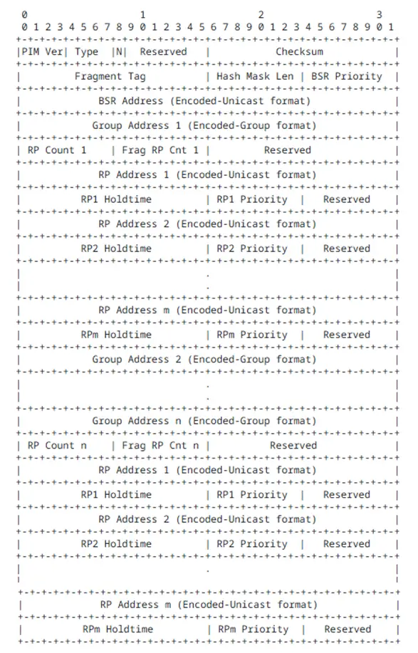
Explanation of Key Parts:
- Type: Refers to the PIM message type field. A value of 4 indicates that it is a Bootstrap Message.
- BSR Priority: The priority of the C-BSR. The range is from 0 to 255, with higher priority C-BSRs being more likely to be elected as the BSR.
- BSR Address: The IP address of the BSR or C-BSR sending the Bootstrap Message. This address is used to identify the current device as a C-BSR or BSR candidate.
RP-SET Section:
The RP-SET is divided into multiple multicast groups, each containing several C-RPs:
- Group Address: Represents a multicast group prefix (e.g., a specific group or a range of groups). Multiple Group records can be included in a single BSM, and each Group can associate one or more candidate RPs.
- RP Address: The IP address of the C-RP (Candidate Rendezvous Point) for the corresponding group.
- RP Priority: The priority of the RP within the same group. The lower the priority value, the more likely it is to be elected as the RP.
- RP Holdtime: The validity period of the RP information (hold time). If the RP information is not updated by a new BSM before the timer expires, the device considers the RP information to be invalid.
(2) C-RP Advertisement Message
Purpose: The C-RP Advertisement message is used by the C-RP to broadcast its information to the BSR, including the multicast group range it can serve, RP address, priority, etc.
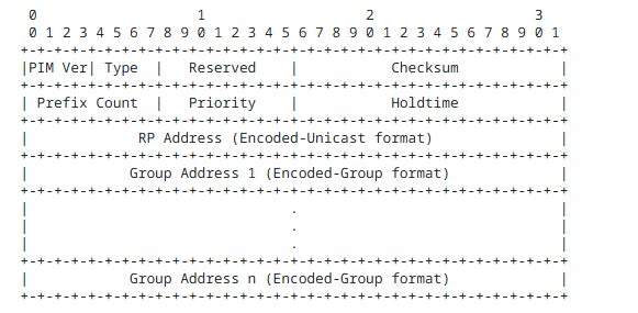
Explanation of Key Fields:
- Priority: The priority of the C-RP. The higher the priority, the more likely the C-RP will be elected as the RP. A value of 0 represents the highest priority.
- Holdtime: The validity period of the Advertisement message. It should be set to 2.5 times the C (a reference value or time period).
- RP Address: The address of the C-RP.
- Group Address: Represents the multicast groups that the C-RP declares it can serve. Multiple multicast groups can be included, indicating the range of groups the C-RP can support.
Summary of the Interactions Among Roles:
- C-BSR broadcasts a Bootstrap Message with information such as its priority to other routers in the network.
- PIM Routers, upon receiving the Bootstrap Message from the C-BSR, start the BSR election process based on the priority and IP address fields, selecting a BSR.
- C-RPs unicast C-RP Advertisement messages to the BSR, announcing their priority, address, and the multicast group range they can serve. After collecting these C-RP Advertisement messages, the BSR generates the RP-SET and encapsulates it in the Bootstrap Message, which is flooded across the PIM-SM domain.
- PIM Routers in the network, based on the RP-SET distributed by the BSR and using a unified algorithm, compute the unique RP address for each specific multicast group.
- Once the network stabilizes, the BSR periodically broadcasts Bootstrap Messages to update the RP-SET.
With an understanding of the device roles, message composition, and interactions in the BSR protocol, you should now have a deep understanding of how BSR works. Next, let’s discuss the two election processes involved.
4. BSR Election Process
- When enabling dynamic RP, C-BSR must also be configured, and the BSR is elected from all C-BSRs.
- In the initial stage, each C-BSR considers itself as the BSR and sends a Bootstrap message to the entire network, which includes the C-BSR’s address and priority.
- Each router receives the Bootstrap messages from all C-BSRs and elects the BSR based on the following rules:
- The candidate with the higher priority wins (the higher the value, the higher the priority).
- If the priorities are the same, the candidate with the larger IP address wins.
- Since all routers use the same election rules, the network will elect the same BSR, and all routers in the network will learn the address of this BSR.
- C-RPs send C-RP Advertisement messages to the BSR, which include the C-RP address, multicast group range served, C-RP priority, and other parameters.
- The BSR collects all C-RP information, compiles it into the RP-SET, encapsulates it into the Bootstrap message, and distributes it to all PIM-SM devices in the network.
5. RP Election Process
Each router, based on the RP-SET distributed by the BSR, calculates and compares the candidates to elect a specific RP for the multicast group, using the following rules:
- The C-RP that matches the longest subnet mask of the multicast group range and the group address that the user has joined wins.
- If the subnet mask length of the matching group range is the same, the C-RP with the higher priority (smaller priority value) wins.
- If the priorities are the same, a hash calculation is performed, and the candidate with the higher result wins.
- If all the above conditions are the same, the C-RP with the larger IP address wins.
Since all routers use the same RP-SET and election rules, the “multicast group – RP” mapping will be consistent across the entire network. Routers will save this mapping to guide subsequent multicast operations.
How to Configure PIM Dynamic RP on Asterfusion Campus Switches
In the previous article, we only introduced how to configure static RP on Asterfusion platforms. In this section, we will explain how to configure PIM Dynamic RP.
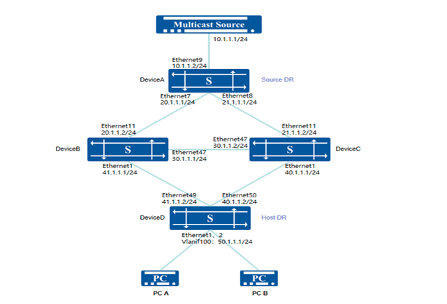
Typical Configuration Topology Conventions:
The host and multicast source are interconnected via four Layer-3 switches, all running OSPF protocol. The host PC is required to be able to request video services from the multicast source over the Layer-3 network. The network uses dynamic RP; if the RP fails, a new RP can be elected to continue providing services. Taking the following topology as an example: Device B and Device C are configured as C-RPs covering the multicast range 224.1.1.0/24. By setting priorities, Device B is elected as the RP, and Device C serves as the backup C-RP. When Device B fails, Device C can be elected as the new RP to continue service.
Procedure:
1. Device A
# Configure an IP address and Loopback0 address for the interface.
- sonic(config)# interface ethernet 9
- sonic(config-if-9)# ip address 10.1.1.2/24
- sonic(config)# interface ethernet 7
- sonic(config-if-7)# ip address 20.1.1.1/24
- sonic(config)# interface ethernet 8
- sonic(config-if-8)# ip address 21.1.1.1/24
- sonic(config)# interface loopback 0
- sonic(config-loif-0)# ip address 120.1.1.217/32
# Configure OSPF neighbors and advertise routes.
- sonic(config)# router ospf
- sonic(config-router)# ospf router-id 120.1.1.217
- sonic(config-router)# network 10.1.1.0/24 area 0.0.0.0
- sonic(config-router)# network 20.1.1.0/24 area 0.0.0.0
- sonic(config-router)# network 21.1.1.0/24 area 0.0.0.0
- sonic(config-router)# network 120.1.1.217/32 area 0.0.0.0
# Configure PIM on the interface, enable multicast routing and forwarding, and enable source-side DR to forward unknown multicast traffic to the CPU.
- sonic(config)# interface ethernet 9
- sonic(config-if-9)# multicast-enable
- sonic(config-if-9)# ip pim
- sonic(config)# interface ethernet 7
- sonic(config-if-7)# multicast-enable
- sonic(config-if-7)# ip pim
- sonic(config)# interface ethernet 8
- sonic(config-if-8)# multicast-enable
- sonic(config-if-8)# ip pim
- sonic(config)# interface loopback 0
- sonic(config-loif-0)# ip pim
- sonic(config)# unknown-multicast trap
#Configure C-BSR, specifying the priority and IP address of the C-BSR.
- sonic(config)# ip pim bsr candidate-bsr source interface loopback 0 priority 200
2. Device B
#Configure an IP address and Loopback0 address for the interface.
- sonic(config)# interface ethernet 11
- sonic(config-if-11)# ip address 20.1.1.2/24
- sonic(config)# interface ethernet 47
- sonic(config-if-47)# ip address 30.1.1.1/24
- sonic(config)# interface ethernet 1
- sonic(config-if-1)# ip address 41.1.1.1/24
- sonic(config)# interface loopback 0
- sonic(config-loif-0)# ip address 120.1.1.80/32
# Configure OSPF neighbors and advertise routes.
- sonic(config)# router ospf
- sonic(config-router)# ospf router-id 120.1.1.80
- sonic(config-router)# network 20.1.1.0/24 area 0.0.0.0
- sonic(config-router)# network 30.1.1.0/24 area 0.0.0.0
- sonic(config-router)# network 41.1.1.0/24 area 0.0.0.0
- sonic(config-router)# network 120.1.1.80/32 area 0.0.0.0
# Configure PIM on the interface, enable multicast routing and forwarding. sonic(config)# interface ethernet 11
- sonic(config-if-11)# multicast-enable
- sonic(config-if-11)# ip pim
- sonic(config)# interface ethernet 47
- sonic(config-if-47)# multicast-enable
- sonic(config-if-47)# ip pim
- sonic(config)# interface ethernet 1
- sonic(config-if-1)# multicast-enable
- sonic(config-if-1)# ip pim
- sonic(config)# interface loopback 0
- sonic(config-loif-0)# ip pim
# Configure C-BSR, specifying the IP address. Configure C-RP, specifying the IP address, covered multicast group address, and priority.
- sonic(config)# ip pim bsr candidate-bsr source interface loopback 0
- sonic(config)# ip pim bsr candidate-rp source interface loopback 0 priority 98
- sonic(config)# ip pim bsr candidate-rp group 224.1.1.0/24
3. Device C
# Configure an IP address and Loopback0 address for the interface.
- sonic(config)# interface ethernet 11
- sonic(config-if-11)# ip address 21.1.1.2/24
- sonic(config)# interface ethernet 47
- sonic(config-if-47)# ip address 30.1.1.2/24
- sonic(config)# interface ethernet 1
- sonic(config-if-1)# ip address 40.1.1.1/24
- sonic(config)# interface loopback 0
- sonic(config-loif-0)# ip address 120.1.1.81/32
# Configure OSPF neighbors and advertise routes.
- sonic(config)# router ospf
- sonic(config-router)# ospf router-id 120.1.1.81
- sonic(config-router)# network 21.1.1.0/24 area 0.0.0.0
- sonic(config-router)# network 30.1.1.0/24 area 0.0.0.0
- sonic(config-router)# network 40.1.1.0/24 area 0.0.0.0
- sonic(config-router)# network 120.1.1.81/32 area 0.0.0.0
# Configure PIM on the interface, enable multicast routing and forwarding. sonic(config)# interface ethernet 11
- sonic(config-if-11)# multicast-enable
- sonic(config-if-11)# ip pim
- sonic(config)# interface ethernet 47
- sonic(config-if-47)# multicast-enable
- sonic(config-if-47)# ip pim
- sonic(config)# interface ethernet 1
- sonic(config-if-1)# multicast-enable
- sonic(config-if-1)# ip pim
- sonic(config)# interface loopback 0
- sonic(config-loif-0)# ip pim
# Configure C-BSR, specifying the IP address. Configure C-RP, specifying the IP address, covered multicast group address, and priority.
- sonic(config)# ip pim bsr candidate-bsr source interface loopback 0
- sonic(config)# ip pim bsr candidate-rp source interface loopback 0 priority 99
- sonic(config)# ip pim bsr candidate-rp group 224.1.1.0/24
4. Device D
# Configure an IP address and Loopback0 address for the interface.
- sonic(config)# interface ethernet 49
- sonic(config-if-49)# ip address 41.1.1.2/24
- sonic(config)# interface ethernet 50
- sonic(config-if-50)# ip address 40.1.1.2/24
- sonic(config)# interface loopback 0
- sonic(config-loif-0)# ip address 120.1.1.122/32
# Configure an IP address for the service interface and enable IGMP functionality. sonic(config)# mcast-snooping enable
- sonic(config)# vlan 100
- sonic(config-vlan-100)# igmp-snooping enable
- sonic(config-vlan-100)# igmp-snooping version 3
- sonic(config)# interface ethernet 1
- sonic(config-if-1)# switchport access vlan 100
- sonic(config)# interface ethernet 2
- sonic(config-if-2)# switchport access vlan 100
- sonic(config)# interface vlan 100
- sonic(config-vlanif-100)# ip address 50.1.1.1/24
- sonic(config-vlanif-100)# ip igmp
# Configure OSPF neighbors and advertise routes.
- sonic(config)# router ospf
- sonic(config-router)# ospf router-id 120.1.1.122
- sonic(config-router)# network 40.1.1.0/24 area 0.0.0.0
- sonic(config-router)# network 41.1.1.0/24 area 0.0.0.0
- sonic(config-router)# network 50.1.1.0/24 area 0.0.0.0
- sonic(config-router)# network 120.1.1.122/32 area 0.0.0.0
# Configure PIM on the interface, enable multicast routing and forwarding. sonic(config)# interface ethernet 49
- sonic(config-if-49)# multicast-enable
- sonic(config-if-49)# ip pim
- sonic(config)# interface ethernet 50
- sonic(config-if-50)# multicast-enable
- sonic(config-if-50)# ip pim
- sonic(config)# interface loopback 0
- sonic(config-loif-0)# ip pim
- sonic(config)# interface vlan 100
- sonic(config-vlanif-100)# multicast-enable
- sonic(config-vlanif-100)# ip pim
# Configure CBSR, specifying the IP address.
- sonic(config)# ip pim bsr candidate-bsr source interface loopback 0
Verify:
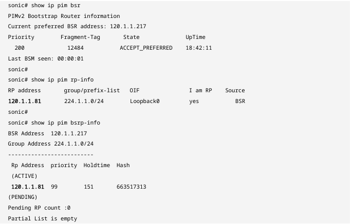
Check the BSR election result and RP address on each device respectively.
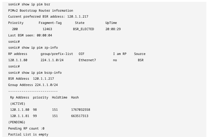
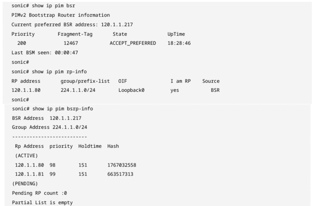
Device A
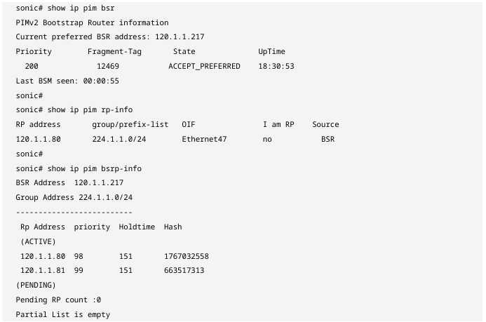
Device B
Device C
Device D
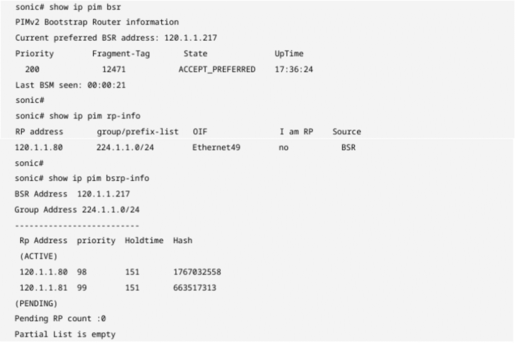
The dynamic RP network converges correctly, with Device A elected as the BSR and Device B elected as the RP for the multicast address range 224.1.1.0/24. At this point, the PC can initiate on-demand services within the 224.1.1.0/24 segment normally, and Device B can establish multicast forwarding entries to guide data forwarding. After Device B fails, the dynamic RP convergence results on each device are as follows:
Device A
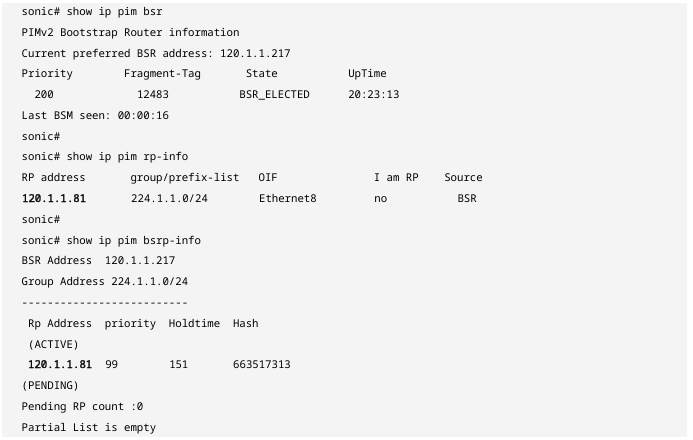
Device C
Device D
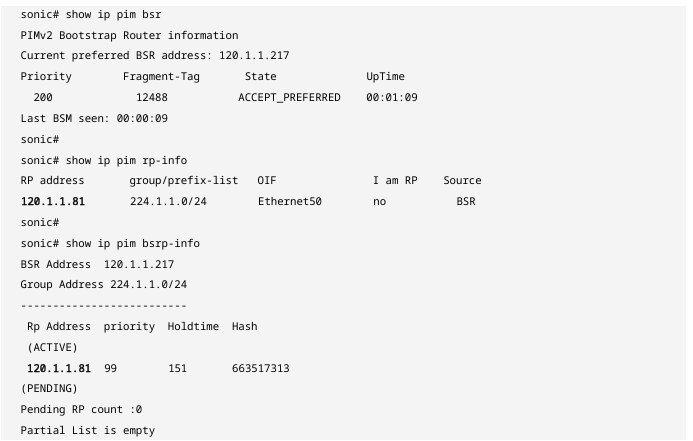
The dynamic RP network has converged correctly, with Device C elected as the RP for the multicast address range 224.1.1.0/24. At this point, the PC can normally initiate on‑demand services within the 224.1.1.0/24 segment, and Device C can establish multicast forwarding entries to guide data forwarding.
Conclusion
The Asterfusion 2025 Q4 Campus Series update is highly optimized for multicast scenarios. By supporting PIM Dynamic RP, it makes management in multicast networks much more convenient while also providing the following benefits:
- Achieving High Availability and Self-Healing: When the core RP fails, the BSR mechanism quickly detects the failure and triggers a recalculation across the network, automatically switching to a backup RP. This millisecond-level fault detection and seamless switching ensure the continuity of critical services such as video conferences and monitoring backhaul.
- Optimizing Large-Scale Network Deployment: In complex campus structures, manually configuring static RPs for each switch is prone to errors and difficult to maintain. Dynamic RP enables “single-point configuration, network-wide synchronization,” greatly reducing operational complexity and eliminating the limitations on network expansion caused by cumbersome configuration logic.
- Eliminating Suboptimal Path Risks: With the flexible group range matching and hash algorithm provided by BSR, administrators can distribute different multicast traffic across multiple C-RPs based on business needs. This not only achieves load balancing but also ensures multicast traffic is always forwarded along the most optimal path according to the network topology.
In conclusion, the introduction of PIM Dynamic RP marks the further maturation of AsterNOS multicast features in enterprise campus networks. Combined with previously supported PIM-SM basic functions, Asterfusion campus switches are now capable of building highly automated and reliable multicast networks, easily meeting the growing multicast traffic demands in the digital transformation of modern enterprises.

Contact US !
- To request a proposal, send an E-Mail to bd@cloudswit.ch
- To receive timely and relevant information from Asterfusion, sign up at AsterNOS Community Portal
- To submit a case, visit Support Portal
- To find user manuals for a specific command or scenario, access AsterNOS Documentation
- To find a product or product family, visit Asterfusion-cloudswit.ch


