Table of Contents
Introduction
John Kim first introduced the Dragonfly network in his paper Technology-Driven, Highly-Scalable Dragonfly Topology. This paper was published in 2008 at the International Symposium on Computer Architecture (ISCA), a leading conference in the field of computer architecture. The paper clearly outlines the core design and theoretical framework of the Dragonfly Topology.
This article will explore the following topics: What is Dragonfly Topology? What is Dragonfly+ Topology? Why are they needed? How do these topologies help reduce costs? What are the existing issues, and why is the Asterfusion platform capable of deploying Dragonfly Topology or Dragonfly+ Topology?
What is Dragonfly Network Topology
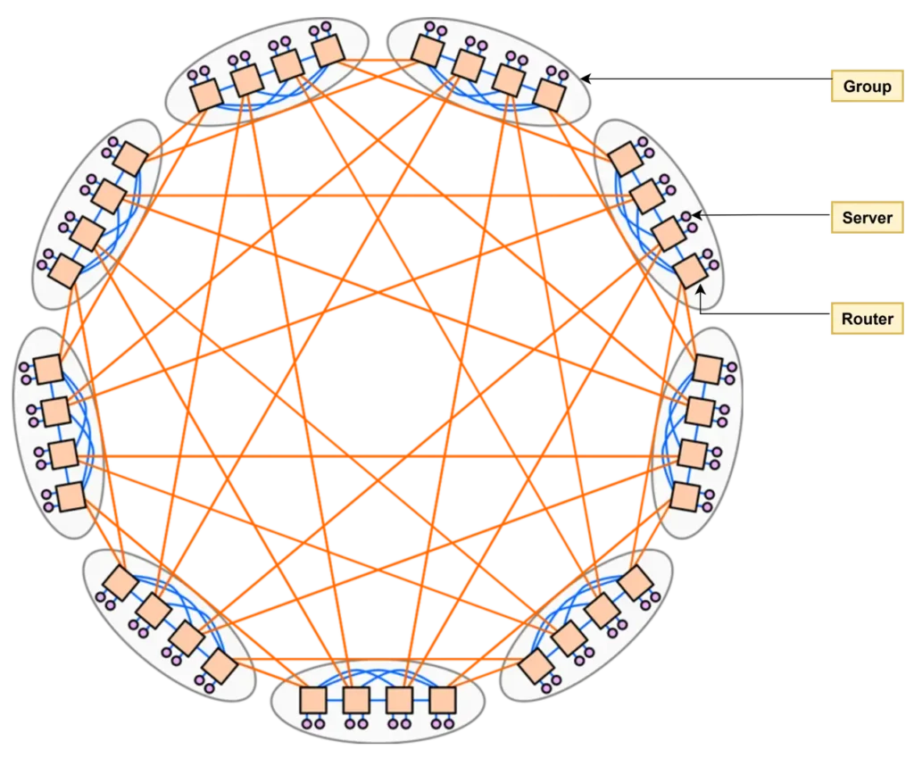
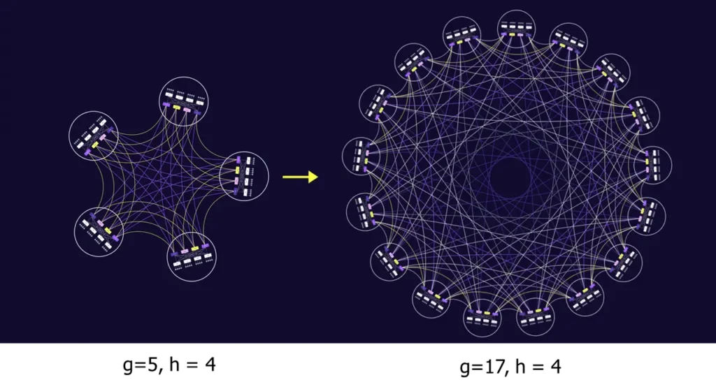
According to the paper by John Kim’s team, in the Dragonfly Network topology, network devices are divided into three tiers: “Router → Group → System.”
Each device in the topology is referred to as a router, regardless of whether it’s originally a switch or a true router.
Multiple routers form a group, with the number of routers in a group denoted as a, and the number of terminals connected to each router denoted as p. Several groups together constitute the entire system, with the number of groups denoted as g.
Intra-group connections, also called local links, are represented by the blue lines in the diagram and are denoted as L. Inter-group connections, also called global links, are represented by the orange lines and are denoted as G. The global links of each router are further denoted as h.
We define these parameters to facilitate the later explanation and discussion of the topology.
In the diagram below, the Dragonfly topology has a = 4, p = 2, g = 9, L = 6, G = 8, and h = 2. If it is a perfectly balanced setup, the above parameters should satisfy a × h = g – 1. Therefore, the diagram represents a Classic Symmetry Dragonfly topology.
Of course, it is also possible for this formula to not be satisfied, in which case other topological forms would emerge.
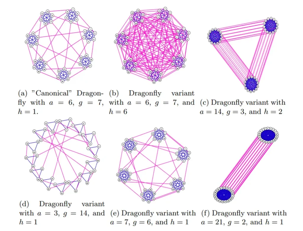
Regardless of the topology form, several groups are connected together using all-to-all links, meaning each group has at least one direct link to each other’s group. The topology within each group can be of any type, and the recommendation in the paper is the flattened butterfly.
From this, it is clear that the Dragonfly network topology concept proposed by J. Kim has many advantages, as detailed below:
- Smaller network diameter: This reduces the number of “hops” between any two points. In a Spine-Leaf architecture, as the number of tiers increases, the number of hops also increases. However, in Dragonfly topology, the number of hops between two points can still be limited to 3 hops on the optimal path.
- Fewer long cables: This minimizes the need for expensive long-distance cabling. Only inter-group connections require long-distance cables, while intra-group connections use short cables.
- Easy scalability: It facilitates adding more capacity in the future. In a large data center with multiple buildings using Spine-Leaf networks, the common approach is to add a super spine to connect these buildings. However, using Dragonfly topology to replace the super spine tier is a better way to connect these buildings together, without the need to add more devices or complicate the tier structure.
- Reliable failover: This ensures normal operation even when part of the network is damaged.
In conclusion, using Dragonfly topology in networks, especially in large-scale AI networks, can effectively improve network efficiency and reduce the total cost of ownership (TCO).
What is Dragonfly+ Topology
In Dragonfly topology, the topology structure within each group can be of any type, but the recommendation is to use the flattened butterfly. According to the IETF Routing in Dragonfly+ Topologies definition, if you use a Spine-Leaf architecture, Clos-like topology, or other bipartite graphs within the group, the resulting topology is referred to as Dragonfly+ Topology.
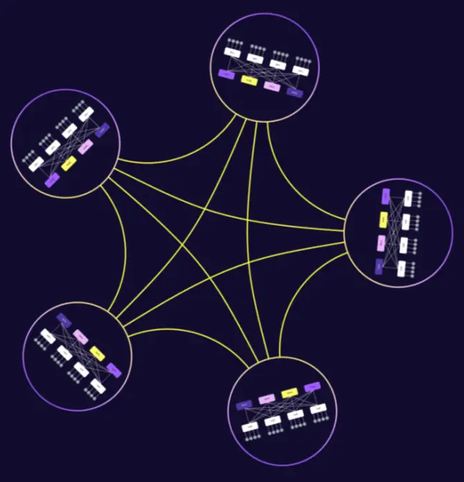
The architecture of Dragonfly+ topology is as follows:
- Internal Structure: A Spine-Leaf topology is used inside each group instead of a full mesh.
- Inter-Group Structure: Maintains a full mesh connection between groups.
- Planes: The “Spine” switches are divided into independent planes.
The main benefit is that, unlike traditional “Super Spine” designs, you don’t need extra switches to connect the groups. You only need to treat each Spine-Leaf architecture as a group and connect the groups using global links.
Dragonfly+ can be connected in two ways depending on your needs:
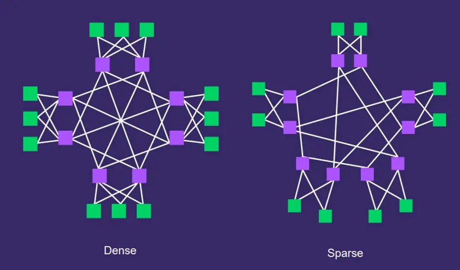
Dense (Full Connection):
Every Spine in a plane is connected to every other Spine in that plane, as shown in the diagram above. The advantage is regular, predictable routing, which is best for 1:1 non-blocking bandwidth. However, the disadvantage is also clear: Harder to expand later. Each Spine in the group must be connected to the Spines of other groups, so if you need to add a new Spine device later, you must establish similar fully interconnected connections.
Sparse Connection:
The Spines are not fully connected; they use a more flexible (often symmetric) layout. The advantage is that it is highly scalable for growing data centers. The downside is lower inter-group bandwidth, meaning not all of the bandwidth is utilized, and the routing becomes more complex, which makes future maintenance more challenging.
The dense mode can evolve into sparse mode. As the network grows, you can add new groups without needing to replace or upgrade the existing routers.
3-Tier CLOS vs. Dragonfly+ Topology for Savings
So how do Dragonfly and Dragonfly+ Topologies help you save costs?
We’ll explain this by comparing traditional Clos architecture with Dragonfly+ topology.
In a large data center, such as one with 4096 racks, without considering the number of pods, we can compare the traditional 3-tier Clos architecture with Dragonfly+. The following cost savings are quite surprising:
- Hardware Savings: Dragonfly+ completely eliminates the need for “Super Spine” switches (about 256 switches).
- Cable Savings: It reduces the number of required optical transceivers by 50% (32,768 fewer modules).
- Lower Latency: It removes one “hop” for traffic moving between groups, speeding up communication.
| 3-Tier CLOS | Dragonfly+ | |
| TOR Switch | 4096 | 4096 |
| Spine Switch | 512 (64 x 8) | 512 (64 x 8) |
| Super Spine Switch | 256 (32 x 8) | – |
| Optical Transceiver(pod interconnection) | 65,536 64 (pods) × 64 (ports) × 8 (planes) × 2 | 32,76864 (pods) × 64 (ports) × 8 (planes) |
Next, let’s assume there are 10 pods. This assumes each POD has 32 racks, and each rack has 32 servers. The spine switch specifications are 64x100G.
After calculation, we can see that in terms of total cost, the traditional 3-tier Clos architecture costs $8,492,800, while the Dragonfly+ network topology only requires $5,612,800, which is just 66% of the cost of a standard 3-tier Clos network.
| CLOS(3-Tier) | Dragonfly+ (10 groups) | |
| POD network cost (32 Leaf + 8 Spine + 256 links) | $529,280 | $529,280 |
| POD qty. | 10 | 10 |
| S2 unit price | $10,000 | 0 |
| S2 qty. | 256 | 0 |
| Inter-group link unit price(100G) | $250 | $250 |
| Inter-group link qty. | 2560 (10x8x32) | 1280 |
| Total cost of network | $8,492,800 | $5,612,800 |
Note: S2 refers to the Super Spine.
When we add another layer on top of the traditional 3-tier Clos (ToR-Spine-Super Spine), forming a massive 4-tier Clos network, and then compare it with the Dragonfly+ network, you will find that the total cost is even lower, at just 32% of the cost compared to a massive 4-tier Clos network.
| CLOS (4-Tier) | Dragonfly+ (100 Group) | |
| Tier1 POD network cost (32 Leaf + 8 Spine + 256links) | $529,280 | $529,280 |
| S2 switch quantity in a Tier 1 POD | 8 | 0 |
| S2-S1 interconnection link qty. | 256 | 12800 |
| Tier 1 POD quantity in a Tier 2 POD | 32 | 100 |
| The cost of a Tier 2 POD | $21,544,960 | 0 |
| The quantity of a Tier 2 POD | 4 | 0 |
| S3 qty. | 8192 | 0 |
| S3-S2 interconnection link qty. | 32768 | 0 |
| Super Spine unit price | $10,000 | 10,000 |
| Inter-group link unit price (100G) | $250 | 250 |
| Total cost of network | $176,291,840 | $56,128,000 |
The Challenges of Dragonfly+ Topology and How to Solve Them
Although Dragonfly+ Topology greatly improves cost and efficiency, like everything, it has both advantages and disadvantages. Dragonfly+ Topology also has some issues:
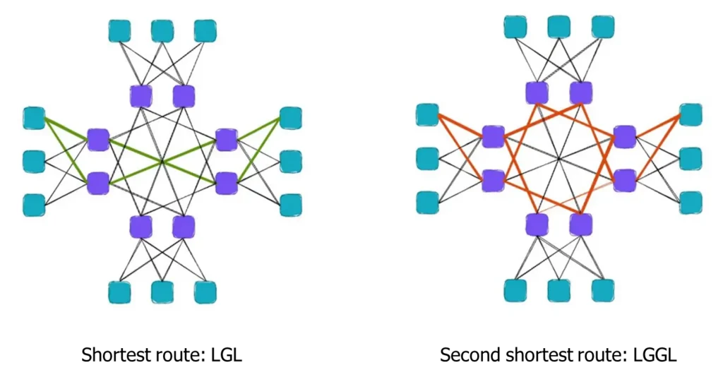
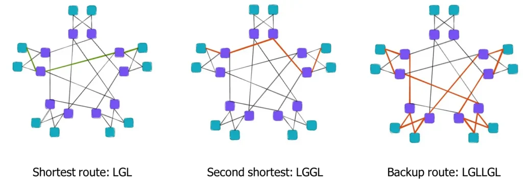
- The Path Problem: There is only one shortest path (LGL) between two groups, but many longer “sub-optimal” backup paths (LGGL or LGLLGL).
- Bandwidth & Delay: How do you use all paths to get full bandwidth without making some packets arrive much later than others?
- Asymmetry: Real-world maintenance and growth often lead to “uneven” connections between groups.
- Fiber Management: Managing thousands of fiber links is a manual labor nightmare.
In dense mode, as shown in the diagram, the green lines represent the optimal path between two points.
Similarly, in sparse mode, the same issue exists, where there is only one optimal path between two groups, and all other paths are sub-optimal.
So how can we solve these issues?
Here are some advanced routing solutions:
- BGP + VRF:
- Assign each group a different ID (AS number).
- Use Virtual Routing (VRF) to separate “Local” and “Core” routes and implement route leaks between them.
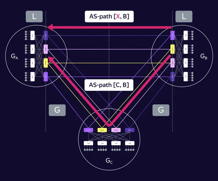
- Path Manipulation:
- Adjust the “AS PATH” attribute to influence best-path selection, so that multiple routes appear to have equal or preferred path lengths.
- LGLLGL Routing:
- Use another intermediate group as a transit route if both the shortest and second shortest routes fail.
Although we can manipulate the AS Path attribute to make devices perceive multiple paths as having equal lengths, ECMP (Equal-Cost Multi-Path) cannot actually be implemented in this case. The core reason is that physical link delays, hop counts, and transmission distances have real differences. ECMP forwards packets under the assumption of “exact equivalence,” which causes issues.
You might think we can use packet spraying and WCMP, but the answer is no:
- Packet spraying is unsuitable:
- It only works in symmetric topologies: Packet spraying works well in symmetric topologies like Spine-Leaf, where packets can be evenly distributed across all links.
- It causes severe packet reordering in asymmetric topologies: In asymmetric topologies like Dragonfly+, packet spraying leads to severe packet reordering issues due to large delay differences between paths.
- Requires deep buffers for reordering: To address reordering, the receiver needs very deep buffers to store and reorder packets, which increases hardware costs and may cause additional latency.
- WCMP is not intelligent enough:
- Theoretically, different weights can be assigned to paths like LGL (Local-Global-Local) and LGGL (Local-Global-Global-Local).
- Weight design is difficult: In complex network topologies and traffic conditions, designing suitable weights is very difficult. Dynamic changes in network traffic and real-time differences in path quality make static weights unsuitable for actual conditions.
The alternative is to use dynamic intelligent routing technology, which can sense the network status and dynamically adjust routing policies for more flexible load balancing.
Asterfusion Data Center platforms support INT-Driven Adaptive Routing (IAR), which adjusts weights for different paths based on real-time detected path metrics.

First, the system enables in-band network telemetry (INT) on switches to monitor delay and load across multiple paths with millisecond-level accuracy. Then, based on these real-time metrics, the decision engine on the switches or controller dynamically adjusts path weights.
On the forwarding plane, the solution uses the WCMP (Weighted Cost Multi-Path) algorithm to execute the strategy: the system automatically allocates more weight to low-latency paths, directing more traffic through them, and reduces traffic on high-latency paths. This mechanism supports flowlet or packet-level fine-grained scheduling, ensuring efficient load balancing while maximizing network bandwidth utilization during dynamic changes.

Another solution to address the limitations of Dragonfly+ topology is Adaptive Routing Based on IPv6 Flow Label.
The switch uses the IPv6 Flow Label as one of the hash inputs to select different paths. There are two implementation schemes:
- Scheme 1: The terminal detects congestion based on ECN signals and assigns a new Flow Label to the flow, forcing the network to perform rerouting.
- Scheme 2: The terminal assigns different Flow Labels based on the semantics of upper-layer applications (such as collective operations, algorithm steps, and data chunks), and the network implements adaptive routing based on the load.
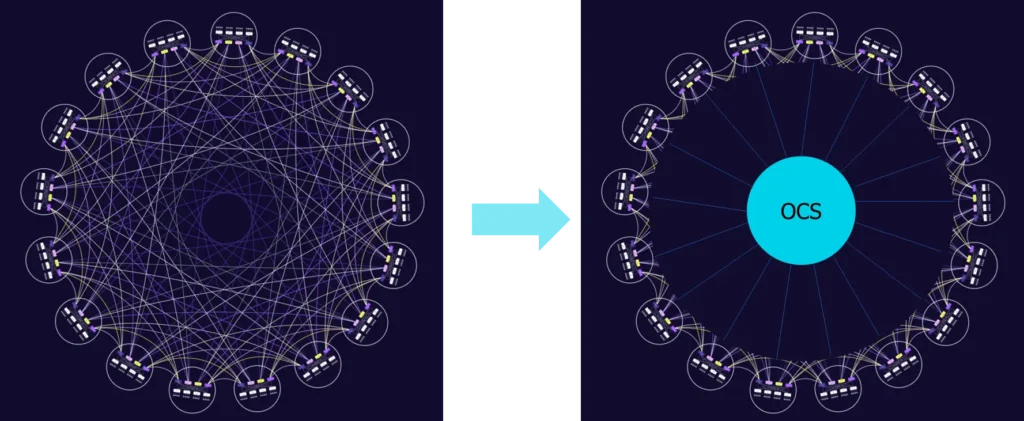
To address physical layer link issues in Dragonfly+ topology, OCS (Optical Circuit Switch) can be introduced. OCS would take over the global link scheduling of Dragonfly+, adapting to the high-bandwidth, low-latency requirements of large-scale AI/HPC clusters. With software, the network physical topology can be adjusted flexibly, without the need for manual cable plugging and unplugging, greatly improving operational efficiency.
Dragonfly+ Use Cases and Future Ready
Dragonfly+ topology has already been used in large-scale AI/HPC scenarios, providing computational network support for many core systems:
- InfiniBand Supercomputers: Introduced by Mellanox in 2017, widely used for high-performance computing.
- Google: Their “Jupiter” network uses an OCS-based Dragonfly+ style design to manage massive traffic with less complexity.
- Yandex: Developing custom SDN controllers to manage these networks.
- Cisco HyperFabric AI: A collaboration with NVIDIA for modern AI workloads.
In summary, in high-density AI scenarios, Dragonfly+ topology can replace the super spine layer. This not only simplifies the architecture but also achieves significant cost optimization. The application of this topology has also brought forward technical challenges, such as the inability to implement ECMP. However, the Asterfusion platform, supporting INT-Driven Adaptive Routing, combines INT and WCMP capabilities, along with fine-grained technologies like flowlets. This allows the deployment of Dragonfly+ topology while addressing its technical shortcomings.
Currently, Dragonfly+ topology has already been applied in some scenarios, and as AI computational demands continue to rise, its use cases will keep expanding. Meanwhile, the value of OCS devices will be further realized, playing an even more significant role in future networks. The combination of Dragonfly+ and OCS will become an important development direction for computational networks in the future.

Contact US !
- To request a proposal, send an E-Mail to bd@cloudswit.ch
- To receive timely and relevant information from Asterfusion, sign up at AsterNOS Community Portal
- To submit a case, visit Support Portal
- To find user manuals for a specific command or scenario, access AsterNOS Documentation
- To find a product or product family, visit Asterfusion-cloudswit.ch


