Table of Contents
Introdcution
In the previous section, we provided an overview of Segment Routing over IPv6 (SRv6) and introduced the first part of how SRv6 works, including the SRH and SRv6 node behaviors. In this article, we will focus on the TLV extensions used in SRv6.

Limitations of Traditional IGP and BGP in Supporting SRv6
In traditional IGP protocols (such as IS-IS and OSPF), the original design goal was primarily to achieve network topology discovery and shortest path computation. Accordingly, the information carried in protocol messages mainly revolves around “reachability” and “metrics.”
However, with the introduction of SRv6, the network no longer only needs to know “where the destination is,” but must further express “which nodes the packet should traverse, what functions should be executed, and how it should be processed,” enabling a level of programmability within the network.
This requires extending the control plane using TLV extensions to carry SRv6-specific semantics beyond traditional routing information.
This introduces a key requirement: the control plane must be able to propagate richer semantic information than traditional routing data, such as:
- SRv6 Locator prefixes supported by each node
- Specific identifiers of various SIDs (e.g., End, End.X, End.DT4, etc.)
- Node capability information (e.g., SRv6 support, maximum SID depth, etc.)
- Service-related attributes (such as policies, weights, service capabilities, etc.)
Such information exceeds the expressive capability of fixed fields in traditional IGP messages. Directly modifying the original protocol structure would not only break compatibility but also make it difficult to support future evolution.
Therefore, TLV extensions in IGP and BGP become the key mechanism to introduce new SRv6 control-plane semantics without changing the base protocol structure.
To address these limitations, introducing the TLV (Type-Length-Value) extension mechanism is a natural and effective approach. TLV extensions allow IGP and BGP to carry richer SRv6-related information without altering their fundamental protocol structures. It provides strong extensibility and backward compatibility, enabling new semantics to be introduced in a flexible and scalable way. As a result, SRv6 can be seamlessly integrated and evolved within existing IGP and BGP frameworks.
This section will introduce the TLV extension approaches and mechanisms of both IGP and BGP in SRv6 scenarios, and explain how they work in coordination with the SRv6 data plane to support Segment List generation and the execution of forwarding behaviors.
In SRv6, TLV extensions act as the unified encoding method for all control-plane enhancements across IGP and BGP.
TLV Extensions in IGP to Carry SRv6-related Information
To support SRv6, IGP (IS-IS) protocols extend the TLV structure to carry SRv6-related information without modifying the original protocol framework. This approach ensures that SRv6 can evolve smoothly within the existing network protocol architecture while maintaining compatibility with legacy devices.
These SRv6 capabilities are advertised through TLV extensions embedded in IGP advertisements.
The SRv6 Locator TLV extension is used to advertise SRv6 Locators along with the associated End SIDs of those Locators. This Locator and SID information is encoded and distributed through IGP TLV extensions.
After receiving this TLV, IS-IS devices with SRv6 capability install the corresponding Locator prefix routes into their local forwarding tables, while devices without SRv6 capability do not install them into the forwarding table.
| Field Name | Length (Unit) | Description |
| Type | 8 bits | Type |
| Length | 8 bits | Length |
| MTID | 12 bits | Multi-Topology Identifier |
| Metric | 32 bits | Metric value |
| Flags | 8 bits | Flags |
| Algorithm | 8 bits | Algorithm |
| Locator Size | 8 bits | Length of the Locator (in bits) |
| Locator | Variable (bits) | Locator prefix |
| Sub-TLV Length | 8 bits | Total length of all sub-TLVs (in bytes) |
| Sub-TLVs | Variable (bytes) | Contained sub-TLVs, e.g., SRv6 End SID sub-TLV |
The deteil SID information is carried within the sub-TLV field.
| Field Name | Length (Unit) | Description |
| Code | 8 bits | Type |
| Length | 8 bits | Length |
| Flags | 8 bits | Flags |
| SRv6 Endpoint Function | 16 bits | SRv6 Endpoint behavior type, e.g., End, End.X (see: SRv6 Endpoint node behaviors) |
| SID | 128 bits | SRv6 SID |
| Sub-Sub-TLV Length | 8 bits | Length of sub-sub-TLVs (in bytes) |
| Sub-Sub-TLVs | Variable (bytes) | Used to further describe the structure, parameters, and behaviors of the SID |
In addition to SID information, SRv6 also carries other important information in different TLV extensions, as shown below:
| Name | Purpose | Carried In |
| SRv6 Capabilities sub-TLV | Used to advertise SRv6 capabilities | IS-IS Router Capability TLV 242 |
| Node MSD sub-TLV | Used to advertise the maximum SID stack depth (MSD, Maximum SID Depth) supported by the device | IS-IS Router Capability TLV 242 |
| IS-IS FAD sub-TLV | Used to advertise the Flexible Algorithm Definition (FAD) | IS-IS Router Capability TLV 242 |
| SR-Algorithm sub-TLV | Used to advertise the algorithms supported by the node | IS-IS Router Capability TLV 242 |
| SRv6 End.X SID sub-TLV | Used to advertise SRv6 SIDs in P2P networks | IS-IS Extended IS Reachability TLV 22; IS-IS IS Neighbor Attribute TLV 23; IS-IS Inter-AS Reachability Information TLV 141; IS-IS Multi-Topology IS TLV 222; IS-IS Multi-Topology IS Neighbor Attribute TLV 223 |
| SRv6 LAN End.X SID sub-TLV | Used to advertise SRv6 SIDs in LAN networks | IS-IS Extended IS Reachability TLV 22; IS-IS IS Neighbor Attribute TLV 23; IS-IS Inter-AS Reachability Information TLV 141; IS-IS Multi-Topology IS Reachability TLV 222; IS-IS Multi-Topology IS Neighbor Attribute TLV 223 |
TLV Extensions in BGP Control Plane
IGP for SR can only allocate SIDs within a single Autonomous System (AS). By properly planning SID allocation within an AS, optimal paths can be achieved inside that domain. However, large-scale networks typically span multiple AS domains. To extend SRv6 semantics beyond a single domain, BGP introduces additional TLV extensions to carry SRv6 control information.
BGP for SRv6 is an extension of BGP for Segment Routing, which enables the allocation of BGP Peer SIDs based on BGP peer relationships and advertises this information to the SDN controller. Subsequently, SRv6 TE Policy uses these BGP Peer SIDs as segments in path computation, thereby enabling optimal cross-domain SRv6 TE paths.
To achieve this, the SRv6 control plane typically consists of the following three key mechanisms:
- BGP-LS with SRv6 Extensions: used for topology and capability advertisement
- BGP SRv6 SID Attributes: used for binding service identifiers with forwarding behaviors
- SRv6 TE Policy: used for path computation and policy distribution
These three components work together across the dimensions of topology, path, and services, forming a complete SRv6 control plane framework.
BGP-LS with SRv6 Extensions: Exporting Information to the SDN Controller
In large-scale SRv6 networks, a centralized “network brain” is typically required to compute paths from a global perspective. BGP-LS is the protocol extension designed to export IGP topology information to an external controller.
Routers within the network disseminate their SRv6 information via IGP. Among them, one or more routers act as BGP-LS speakers, collecting IGP information and exporting both topology and SRv6-related data to an SDN controller via the BGP-LS protocol. Based on this information, the controller runs CSPF (Constrained Shortest Path First) algorithms to compute optimal paths, generates Segment Lists, and delivers them to the headend nodes via BGP or NETCONF.
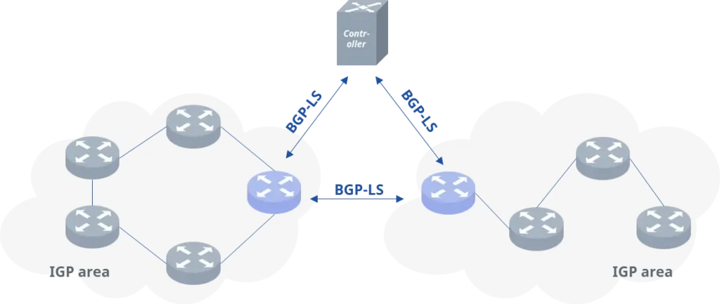
BGP-LS packages and advertises topology information to the controller using NLRI (Node/Link/Prefix) along with Attributes (which include SRv6 information).
| NLRI Type | Content | Purpose |
| Node NLRI | Router-IDSR CapabilitySRv6 Locator(extension)Node Flags | Represents network nodes and their capabilities |
| Link NLRI | Metric(IGP cost)Max Link BandwidthUnreserved BandwidthSRLG (Shared risk link group)Adjacency SID(SR / SRv6) | Represents link information |
| Prefix NLRI | Prefix SIDRoute TypeLabel/Algorithm | Represents prefixes advertised by nodes |
Taking the structure of Link NLRI as an example:
| NLRI | Network Layer Reachability Information |
|---|---|
| Local Descriptor (Node) | The local descriptor consists of the local Router ID, the local AS number, and the BGP-LS ID |
| Remote Descriptor | The remote descriptor consists of the neighbor's Router ID and the neighbor's AS number. |
| Link Descriptor | The link descriptor contains the addresses used by the BGP session. |
| Link Attribute | Link Information: Part of the Link NLRI |
| Administrative Group | Administrative group attribute of the link |
| Max Link BW | Maximum link bandwidth |
| Max Reservable Link BW | Maximum reservable link bandwidth |
| Unreserved BW | Available (unreserved) link bandwidth |
| Shared Risk Link Group | Shared risk link group |
| SRv6 End.x | The adjacency SID to reach the neighbor; represents the Peer-Adj-SID |
BGP-LS centralizes the distributed link-state and SRv6 SID information of the network, enabling the controller to compute Segment Lists based on a global view, thereby achieving fine-grained traffic engineering and path orchestration.
BGP VPN with SRv6 SID Attributes: Binding Services to Forwarding Behaviors
In the SRv6-based VPN service model, the traditional label-based forwarding mechanism used in MPLS L3VPN/EVPN is replaced by SRv6 Segment Identifiers (SIDs). To achieve precise binding between service prefixes and SRv6 forwarding behaviors, BGP introduces the SRv6 SID Attributes mechanism by extending BGP Path Attributes.
In this mechanism, the PE (Provider Edge) node allocates a unique Service SID for each VPN instance locally and binds it to a specific SRv6 Endpoint Behavior, such as End.DT4 or End.DT6. When advertising VPN routes, both the VPN route and the associated SID are carried together, enabling the binding between the service prefix and the SRv6 forwarding behavior.
When a PE node advertises VPN routes to a remote peer, it includes both the service prefix and the SRv6 SID Attributes in the BGP Update message. For example:
- VPN route prefix: 10.1.1.0/24
- Associated SRv6 SID: 2001:db8:100:1::A
- Endpoint Behavior: End.DT4
The SRv6 SID Attributes adopt a nested TLV structure, as illustrated below:
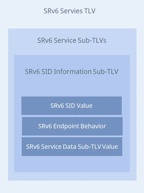
The SID information is carried in the SRv6 SID Information Sub-TLV, with the following format:
| Field Name | Length (Unit) | Description |
| SRv6 Service Sub-TLV Type | 8 bits | TLV type; value 1 indicates SRv6 SID Information Sub-TLV |
| SRv6 Service Sub-TLV Length | 16 bits | Length of this sub-TLV |
| Reserved1 | 8 bits | Reserved field, set to 0 |
| SRv6 SID Value | 16 bytes | SRv6 SID value |
| SRv6 SID Flags | 8 bits | Reserved flag field, currently undefined |
| SRv6 Endpoint Behavior | 16 bits | SRv6 behavior; cu |
After receiving the route, the remote PE establishes a mapping between the prefix and the SID in its local forwarding table. When service traffic matches the VPN prefix, the ingress PE performs SRv6 encapsulation based on this mapping, inserting the corresponding SID into the destination address field of the outer IPv6 header. The packet is then forwarded across the SRv6 network according to the SID. Upon reaching the target PE, the node executes decapsulation and subsequent forwarding based on the Endpoint Behavior associated with the SID.
BGP SRv6 TE Policy: Path Computation and Policy Distribution
The SDN controller obtains a global view of the network topology through the previously described protocol extensions. Based on service requirements (such as bandwidth, latency, link utilization, etc.), it computes an optimal path that satisfies given constraints. The SRv6 Segment List defines an end-to-end path, enabling fine-grained traffic engineering.
An SRv6 Segment List consists of an explicit list of SIDs (Segment Identifiers), where each SID represents a specific function or forwarding behavior in the network. For example:
SID List = [SID_B, SID_C, SID_D]
This SID list defines a deterministic path from the source node (headend) to the destination node (endpoint), which is then used for packet forwarding.
After the policy is generated, it is advertised via the BGP SR Policy extension (SAFI 73), enabling distributed propagation across the network.
In the BGP Update message, the following key information is carried:
NLRI
- Endpoint: the destination of the policy (SRv6 tunnel endpoint address)
- Color: policy identifier, used to distinguish different services or traffic types
Tunnel Encapsulation Attribute
- SRv6 SID List: a sequence of SIDs forming the path
- Candidate Path
- Policy identifiers (Color and Endpoint)
- Binding SID (policy identifier SID)
When the headend receives the SR Policy, it installs the policy into the local SR Policy table and associates it with local service policies, thereby enabling fine-grained traffic steering.
Process Summary
The overall workflow is as follows: IGP propagates basic topology and SRv6 information within the network. BGP-LS then collects and exports this information to the controller. Based on the global network view, the controller computes optimal paths and distributes policies via BGP. At the same time, BGP is responsible for binding service routes with SIDs.
Finally, the ingress node performs SRv6 encapsulation based on this information, inserting the SID list into the IPv6 header. Each node in the network forwards or processes the packet according to the instructions carried in the SID list.
In essence, this section highlights that SRv6 requires a more expressive control plane. This is achieved by introducing TLV-based extensions into IGP and BGP, enabling both path orchestration and service binding.
Next Article: The difference between SRv6 TE and SRv6 BE.
Request a demo or need assistance ?
Fill out the form, and we’ll reach out to you today !


