Table of Contents
Ⅰ. Introduction
Building on our previous discussion regarding PTP Design Best Practices for Media & Entertainment IP Networks, this article will dive into how Enterprise SONiC strategically architects its PTP profiles.
A PTP profile represents a predefined set of configuration rules and timing behaviors designed for a specific synchronization scenario. It standardizes how devices participating in IEEE 1588 Precision Time Protocol operate within a particular environment, ensuring that clocks from different vendors can maintain accurate and consistent time alignment.
Each profile defines the functional capabilities, parameter constraints, and operational procedures required for devices in a given role or network topology. By standardizing these parameters, PTP profiles help guarantee deterministic timing performance and interoperability across heterogeneous deployments, which is critical in distributed infrastructures.
Beyond simply restricting the configurable parameters defined in the base IEEE 1588 Precision Time Protocol specification, many profiles also introduce additional guidelines or optimization mechanisms tailored to real-world operational requirements. These extensions address the stringent timing demands found in environments such as telecommunications networks, professional broadcast infrastructures, and large-scale data center fabrics.
Ⅱ. PTP Profile Classification
Campus switches can support multiple PTP profiles designed for different synchronization scenarios. These profiles are generally divided into three categories: General Purpose, Telecom, and Media.
Each profile defines specific parameter ranges, clock behaviors, and message exchange mechanisms. This standardization ensures interoperability between multi-vendor devices while maintaining reliable and precise time synchronization.
In programmable switching platforms, Asterfusion Enterprise SONiC supports multiple PTP operational modes, including Boundary Clock (BC) and Transparent Clock (TC), allowing switches to participate in different timing architectures across campus, telecom, and media networks.
General Purpose Profile
The General Purpose profile is designed for standard Ethernet or IP networks. It provides flexible timing configuration without focusing on a specific industry requirement.
This profile is commonly used in enterprise networks or environments where moderate time synchronization accuracy is sufficient. A typical example is the default profile defined in IEEE 1588.
In these scenarios, switches running Enterprise SONiC can operate as PTP boundary clocks or transparent clocks, enabling reliable time distribution across enterprise and data center infrastructures.
Telecom Profile
The Telecom profile is defined by International Telecommunication Union for carrier transport networks and mobile communication systems.
It introduces strict requirements for time, phase, and frequency accuracy. The profile also specifies clockClass behavior and domain number rules to support hierarchical telecom synchronization architectures.
In 4G and 5G TDD networks, precise synchronization is essential for base station time-slot alignment. Campus switches therefore support telecom profiles such as G.8275.1 (Full Timing Support) and G.8275.2 (Partial Timing Support).
These profiles can also work together with Synchronous Ethernet to improve frequency stability. Platforms running Enterprise SONiC can integrate these capabilities for telecom transport and mobile backhaul networks.
Media Profile (Media / SMPTE / AVB)
The Media profile is designed for professional broadcast and IP-based audio-video production networks. It ensures accurate synchronization of video frames, audio streams, and control signals.
Media networks usually require sub-microsecond timing accuracy and rely on multicast communication mechanisms. These profiles are commonly used in broadcast studios, OB vans, and media production networks.
For example, SMPTE ST 2110 environments rely on PTP to provide a unified time reference across the entire network.
Ⅲ. PTP Profile Specific Introduction
General Purpose PTP Profile
IEEE 1588v2
The IEEE 1588v2 Default Profile is the most general-purpose PTP profile and serves as the foundation for other industry-specific profiles, such as G.8275.x, AES67, and SMPTE-2059-2. It is designed to provide high-precision time synchronization over standard IP or Ethernet networks, ensuring interoperability across vendors. This profile is based on the IEEE 1588v2 standard and is widely used in enterprise LANs, data centers, and general Ethernet environments.
The Default Profile employs a Master/Slave clock architecture, with the BMCA (Best Master Clock Algorithm) automatically selecting the master clock in the network. The Master Clock provides a unified time reference to Slave Clocks, ensuring time consistency across the network.
Clock Type
In IEEE 1588v2, the clock type of a PTP network node defines its role and function in time synchronization. The main types are Ordinary Clock (OC), Boundary Clock (BC), and Transparent Clock (TC).
- Ordinary Clock (OC)
The ordinary clock is the most basic PTP clock type, typically with a single PTP port. It can act as either a Master or a Slave. OC is suitable for single-port devices or small networks. It can provide a time reference or receive synchronization from an upstream clock, and participates in master clock selection in the network through the BMCA (Best Master Clock Algorithm).
- Boundary Clock (BC)
The Boundary Clock (BC) is a multi-port device, with each port capable of acting as a Slave to receive upstream synchronization and as a Master to distribute time to downstream ports. BC is primarily used to isolate delay accumulation across network segments, improving synchronization accuracy in large networks.
- Transparent Clock (TC)
The Transparent Clock (TC) differs from OC and BC in that it neither provides a time reference nor uses received synchronization to adjust its local clock. TC only measures the delay of PTP messages through the device or link and attaches this delay information to the message for downstream nodes, reducing end-to-end synchronization error accumulation.
PTP Messages and Communication Mechanism
Time synchronization in the Default Profile is achieved using Sync, Follow_Up, Delay_Req, Delay_Resp, Pdelay_Req / Pdelay_Resp and Announce messages:
- Sync / Follow_Up: Master sends timestamp information to slaves.
- Delay_Req / Delay_Resp: Slaves measure one-way delay to compensate for network latency.
- Pdelay_Req / Pdelay_Resp: Neighboring PTP devices measure link delay between directly connected peers, enabling per-hop delay compensation in P2P mode.
- Announce: Master broadcasts its status for BMCA master election.
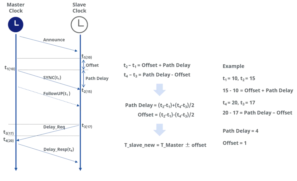
These messages allow endpoints to calculate local clock offset accurately and adjust their time, achieving sub-millisecond synchronization.
The Default Profile supports both multicast and unicast communication, providing flexible network deployment, PTP messages can be transported over L2 Ethernet or IP networks, enabling cross-vendor interoperability and hybrid network environments.
Media PTP Profile
In modern IP-based broadcast networks, high-precision audio-video synchronization and frame-level alignment are typically achieved using AES67 or SMPTE-2059-2 PTP profiles. Both profiles are based on IEEE 1588v2 but are optimized for their respective application scenarios. Compared with telecom network profiles such as G.8275.x, broadcast media profiles do not impose strict constraints on PTP clock parameters; their design goal is to meet the synchronization accuracy required for audio and video streams, rather than full network telecom-grade timing.
AES67 Profile
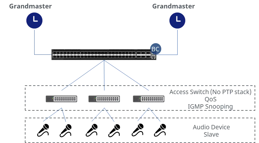
AES67 targets audio networking interoperability, focusing on synchronization and clock distribution for audio streams, typically requiring sub-millisecond synchronization accuracy.
Clock Type
- Master Clock: Provides the primary time reference, typically hosted by an audio gateway or core switch.
- Slave Clock: Audio endpoint devices synchronize to the network via PTP.
PTP Messages and Communication Mechanism
AES67 supports both unicast and multicast synchronization messages. Multiple Masters can coexist, with one master selected via PTP’s BMCA. Endpoints act as Slaves to receive synchronization, and intermediate network nodes do not need to process PTP messages.
Typical Use Case
SMPTE-2059-2
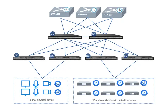
SMPTE-2059-2 targets video IP networks such as SMPTE ST 2110 streaming systems, emphasizing video frame synchronization with sub-microsecond precision.
Clock Type
- Master Clock: Provides the primary time reference, typically hosted by an audio gateway or core switch.
- Slave Clock: Audio endpoint devices synchronize to the network via PTP.
PTP Messages and Communication Mechanism
SMPTE-2059-2 supports both unicast and multicast synchronization messages. In video synchronization scenarios such as SMPTE ST 2110, multicast communication is the primary method, allowing synchronization information to be distributed simultaneously to a large number of endpoints, ensuring frame-level alignment across multiple video streams.
SMPTE Media TLV
In broadcast media networks, beyond basic time synchronization, the SMPTE-2059-2 profile also supports SM-TLV (SMPTE Media TLV) extensions, which carry metadata related to media synchronization to enable frame-level alignment across multiple devices.
First, devices support system frame rate configuration. Under the ST 2059-2 profile, the frame rate is represented by a numerator and denominator, calculated as:
Frame Rate (fps) = numerator / denominator
The numerator indicates the maximum number of frames per unit time, while the denominator is a normalization factor. When configured, the device includes the frame rate information in PTP messages via SM-TLV. The receiving device calculates the duration of each frame based on numerator/denominator, achieving precise frame-level synchronization of video streams.
| System Frame Rate | Numerator | Denominator | Notes |
| 29.97fps | 30000 | 1001 | Used for North American broadcast video |
| 30fps | 30 | 1 | Standard progressive frame rate |
| 25fps | 25 | 1 | European broadcast standard |
| 24fps | 24 | 1 | Film standard |
Second, devices support Drop-frame timecode configuration to correct timing deviations for non-integer NTSC frame rates (29.97 fps). Drop-frame does not discard video frames; it only skips timecode numbers, keeping the timecode aligned with real clock time over each hour. This ensures accurate frame-level synchronization, allowing multiple devices to maintain ±0.5 µs frame alignment.
Additionally, devices can include color-frame information in SM-TLV messages, marking each frame’s type, number, and color sequence. This allows receiving endpoints to identify both frame number and color type accurately. Video streams from multiple cameras or devices can then be aligned based on Frame + Color, preventing misalignment or color deviations during scene switching or video compositing.
Typical Use Case
Telecom PTP Profile
G.8275.1 Profile
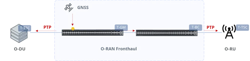
G.8275.1 is designed for mobile cellular systems (such as 4G/5G) and telecom transport networks that require highly accurate time and phase synchronization. The profile adopts a Full Timing Support architecture, meaning that every intermediate node in the network must actively participate in PTP processing. All nodes are required to recover and regenerate timing information. Consequently, Transparent Clocks (TC) are not permitted in this model; instead, Telecom Boundary Clocks (T-BC) are used to perform hop-by-hop timing correction and redistribution.
Clock Type
G.8275.1 defines telecom-specific clock roles:
- T-GM (Telecom Grandmaster)
The T-GM provides the primary time reference for all downstream devices in the network. Its time source must be traceable to a Primary Reference Time Clock (PRTC). When in the locked state, both phase and frequency must remain traceable to the PRTC. If the external phase reference is lost, the T-GM may enter holdover mode to maintain synchronization accuracy for a defined period. The system may dynamically adjust PTP clock priorities based on the GM lock status to ensure optimal grandmaster selection.
- T-TSC (Telecom Time Slave Clock)
A T-TSC typically enables only one PTP interface within the same domain and operates exclusively as a slave clock. It is commonly deployed at cell sites or time-sensitive endpoints to receive distributed time and phase information.
- T-BC (Telecom Boundary Clock)
A T-BC recovers timing from an upstream node and regenerates synchronization messages for downstream nodes, performing hop-by-hop timing correction and maintaining synchronization accuracy throughout the network.
PTP Domain
In a G.8275.1 network, the PTP domain number is strictly limited to the range 24 to 43 (inclusive). Restricting the domain range prevents conflicts with other PTP profiles or general-purpose networks, ensuring isolation and manageability of telecom synchronization domains.
PTP Messages and Communication Mechanism
In G.8275.1 networks, PTP messages are encapsulated directly in Layer 2 Ethernet frames using the IEEE 1588 EtherType (0x88F7). Synchronization messages are transmitted using multicast MAC addresses. The default multicast addresses include:
- 01-1B-19-00-00-00 (PTP event messages)
- 01-80-C2-00-00-0E (link-local multicast for certain control messages)
G.8275.1 supports only Layer 2 Ethernet transport and does not allow IP-based encapsulation. This design minimizes protocol stack processing overhead and network latency uncertainty, ensuring high-precision and low-jitter time and phase distribution within telecom synchronization networks, especially when operating in conjunction with SyncE architectures.
Typical Use Case
G.8275.2 Profile
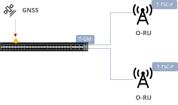
G.8275.2 is designed for telecom transport networks that require accurate time and phase synchronization but cannot guarantee PTP support at every network node. The profile adopts a Partial Timing Support architecture, allowing intermediate nodes that do not support PTP. This makes it suitable for deployment over existing IP transport networks or across heterogeneous domains.
Unlike G.8275.1, G.8275.2 does not require every node to recover and regenerate timing information. Synchronization is maintained between PTP-aware boundary nodes, while intermediate non-PTP devices perform standard IP forwarding only. This approach significantly improves deployment flexibility and reduces the need for full network infrastructure upgrades.
Clock Types
G.8275.2 defines telecom clock roles adapted for partial timing support networks:
- T-GM (Telecom Grandmaster)
The T-GM provides the primary time reference for the synchronization domain and is typically traceable to a PRTC. When locked, both time and phase remain traceable to the reference source. In the event of reference loss, it may enter holdover mode to maintain short-term stability.
- T-TSC-P (Telecom Time Slave Clock – Partial Support)
The T-TSC-P operates as a slave clock at time-sensitive endpoints. Its synchronization path may traverse non-PTP-aware nodes, requiring enhanced tolerance to packet delay variation.
- T-BC-P (Telecom Boundary Clock – Partial Support)
The T-BC-P receives timing from an upstream node and regenerates synchronization messages toward downstream nodes. Unlike the T-BC in G.8275.1, its synchronization chain may cross non-PTP-aware intermediate devices.
PTP Domain
In a G.8275.2 network, the PTP domain number is restricted to the range 44 to 63 (inclusive). By separating the domain ranges of G.8275.1 and G.8275.2, both profiles can coexist on the same physical network without conflicts, ensuring isolation and manageability of different synchronization domains.
PTP Messages and Communication Mechanism
ITU-T G.8275.2 supports both unicast and multicast PTP message transmission mechanisms. In practical telecom transport network deployments, since it is designed for IP network environments that do not provide full PTP awareness across all nodes, unicast negotiation is typically adopted to improve scalability and traffic controllability.
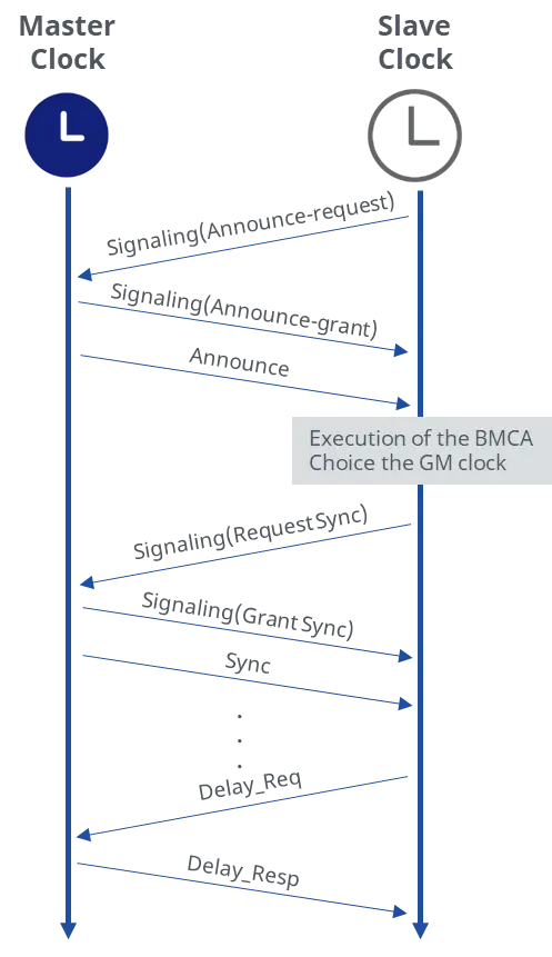
A slave clock initiates unicast discovery by sending a Signaling message to one of its configured master clocks requesting the master send unicast Announce messages to the slave. The request includes the desired rate for the Announce messages and the duration over which the messages should be sent.
If the master can support the request it replies with a Signaling message indicating that the session for unicast Announce messages has been granted. From this point on, the master sends unicast Announce messages to the slave at the rate requested.
A slave will generally establish an Announce message session with at least two master clocks. The slave then uses the Announce messages it receives from all masters as input to the BMCA that determines which master clock is the best source for information. The selected master becomes the grandmaster clock to the slave. The slave then sends additional Signaling messages to the grandmaster to request unicast delivery of Sync and Delay_Resp messages.
Assuming the grandmaster clock has sufficient resources, the request is granted and unicast Sync and Delay_Resp messages are sent from the grandmaster to the slave. As with the Announce messages, the rate at which the Sync and Delay_Resp messages are sent and the duration of the unicast sessions is requested by the slave in the initial Signaling messages.
Typical Use Case
PTP Profile Key Parameter Comparison Table
| Profile | Clock Type | Communication | Message Mechanism | Delay Mechanism | Synchronization Accuracy | Typical Use Cases |
| IEEE 1588v2 Default | Master / Slave | Unicast / Multicast | Sync, Follow_Up, Delay_Req, Delay_Resp, PDelay_Req, PDelay_Resp, Announce | E2E/P2P | Sub-millisecond | Enterprise LAN, Data Center, General Ethernet |
| G.8275.1 | T-GM, T-BC, T-TSC | Ethernet | Sync, Follow_Up, Delay_Req, Delay_Resp, Announce | E2E | Nanosecond-level | Telecom core network, 4G/5G base stations, carrier networks |
| G.8275.2 | T-GM, T-BC-P, T-TSC-P | Unicast | Sync, Follow_Up, Delay_Req, Delay_Resp, Announce, Signalling | E2E | Nanosecond-level | Telecom core network, TDD / 5G networks, OC for small edge nodes |
| AES67 | Master / Slave | Unicast / Multicast | Sync, Follow_Up, Delay_Req, Delay_Resp, Announce | E2E | Sub-millisecond | IP audio broadcast, studio, AV transmission |
| SMPTE-2059-2 | Master / Slave | Unicast / Multicast | Sync, Follow_Up, Delay_Req, Delay_Resp, Announce + SM-TLV | P2P | Sub-millisecond | IP video production, ST2110 media network, OB van, studio frame-level sync |
Ⅳ. How Asterfusion Devices Support PTP and Key Features
Asterfusion switches are designed to bridge the gap between complex PTP protocols and practical deployment, covering scenarios from Campus Networks to Data Centers.
- Flexible PTP Clock Types: Full support for configuring devices as Boundary Clock (BC) or Transparent Clock (TC) to adapt to your network topology.
- Comprehensive Profile Support: Seamless integration with major PTP profiles including G.8275.1 (Telecom) and SMPTE 2059-2 (Broadcast), supporting both E2E and P2P delay mechanisms.
- High-Precision Standards: Fully compliant with IEEE 1588v2 and SMPTE 2059-2, delivering Class A/C accuracy for critical timing requirements.
- Versatile Deployment: From enterprise campus to high-performance data center, Asterfusion delivers robust PTP functionality across the board.
Feature List
The table below outlines the PTP feature set supported across Asterfusion Campus switches. As shown, our Enterprise SONiC-based AsterNOS offers comprehensive support for a wide range of PTP profiles, including all the key types previously discussed.
| PTP Feature | Detail Information |
| Multi-instance | Supports up to 4 PTP instances |
| Profile | SMPTE-2059-2/1588v2/G.8275.1/G.8275.2/AES67 |
| Clock type | oc/bc/tc/t-gm/t-bc/t-tsc/t-tc/t-bc-p/t-tsc-p |
| Clock step | one_step/two_step |
| Transport mode | UDPv4/UDPv6/Ethernet/Unicast/Multicast |
| Delay mode | E2E/P2P |
| GNSS grandmaster | |
| PTP clock parameters | Dynamic adjustment / Static configuration |
| SM-TLV | |
| SyncE |
Switch List
Across the entire Asterfusion product portfolio, PTP support is a standard feature. However, PTP classifications may vary by model. Please refer to the table below to select the product that best fits your requirements.
| Product | PTP Time Synchronization ITU Classification | Description |
| CX306P-48Y-M-H | Class C | • 48×25 Gb SFP28, 6×100 Gb QSFP28 • Support IEEE1588v2 and SyncE, GNSS receiver, 1PPS, ToD, 10MHz timing interfaces |
| CX102S-8MT-M-S CX102S-8MT-M-SWP CX102S-16GT-M-SWP CX102S-16GT-DPU-M-SWP | Class A | • Support different access rates and enabling flexible deployment across diverse application scenarios• Optional PTP module supports SyncE |
| CX204Y-24GT-M-S CX204Y-24GT-M-SWP2 CX204Y-24GT-M-SWP4 CX206Y-48GT-M-H CX206Y-48GT-M-HWP4 CX206Y-48GT-M-HWP8 CX206P-24S-M-H CX202P-24Y-M-H CX206P-48S-M-H CX308P-48Y-M-H CX532P-M-H CX732Q-M-H CX206Y-48GT-M-H | Class C |
Contact US !
- To request a proposal, send an E-Mail to bd@cloudswit.ch
- To receive timely and relevant information from Asterfusion, sign up at AsterNOS Community Portal
- To submit a case, visit Support Portal
- To find user manuals for a specific command or scenario, access AsterNOS Documentation
- To find a product or product family, visit Asterfusion-cloudswit.ch


