Table of Contents
Whether it’s a conventional data center or a modern cloud-based one, a shared necessity exists: high availability.
Concurrently, a mutual challenge persists: the potential for a single point of failure within the network. Physical networking aimed to establish highly reliable connections between devices by employing LAG (Link Aggregation) technology. This ensures high availability of links between servers and switches or between switches themselves. However, LAG technology is not without its flaws and cannot entirely eliminate equipment failure risks.
Consequently, there’s a need for technology that expands the original singular connections between devices to multiple connections, while still guaranteeing multi-device redundancy and multi-link redundancy. Moreover, this technology must ensure robust intercommunication between devices. Enter MC-LAG or M-LAG(Multi-Chassis Link Aggregation), the focal point of this article. As an extension of LAG, it is crucial to comprehend the workings of LAG prior to understanding MC-LAG’s principles.
What is LAG (Link Aggregation group)?
Link Aggregation group, often referred to as Port Channel, is an innovative technology that combines multiple physical connections into a single logical port at the data link layer. This process effectively increases bandwidth and enhances link redundancy. When utilized for connecting servers and switches, the physical topology can be observed in the illustration below.
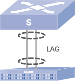
In order to facilitate dynamic aggregation of physical links, Link Aggregation requires the implementation of LACP (Link Aggregation Control Protocol) between two devices for seamless negotiation.
what is LACP (Link Aggregation Control Protocol)?
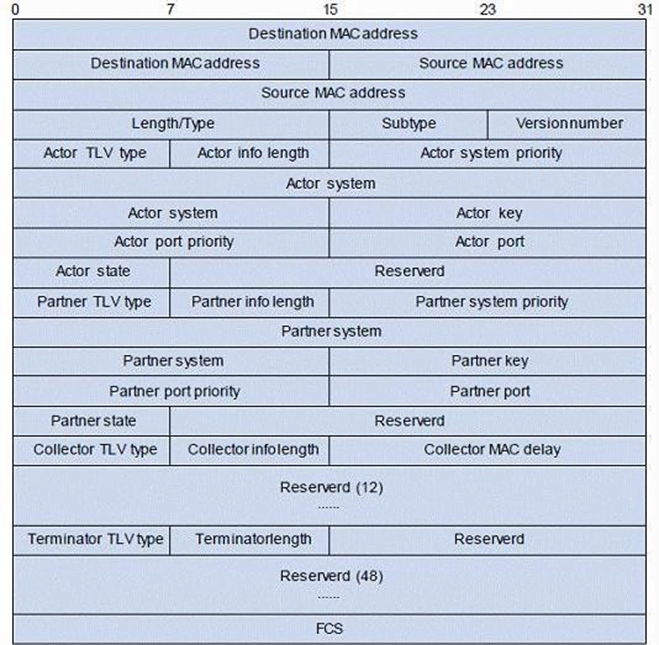
LACP(Link Aggregation Control Protocol) is an integral part of the IEEE 802.3ad standard and functions as a method to manage combining several physical ports into one cohesive logical channel. This protocol enables a network device to automatically form bundles of links by sending LACP packets to its corresponding device.
LACP provides multi-link redundancy through multi-link load balancing executed by hashing information such as quintuples of packets. As a result, all link bandwidths can be efficiently utilized. Once the aggregated link is established, LACP diligently maintains the link state and auto-adjusts or dissolves the aggregated link should any changes in aggregation conditions occur.
LAG offers redundancy between one-to-one devices by allowing for an uninterrupted flow of data even if a physical link in the aggregated group disconnects. However, it doesn’t address data path interruptions caused by switch downtime. In response, MC-LAG was developed to solve this issue.
What is MC-LAG(mlag)?
MC-LAG extends the original link aggregation technology from one-to-one devices to one-to-many devices, as depicted in the illustration below.
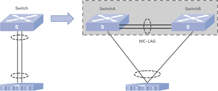
With node redundancy in place, traffic is appropriately load-balanced between two switching devices using a hash algorithm. Additionally, MC-LAG has a built-in anti-loop mechanism, eliminating the need for complex STP protocols or Layer 3 routing and forwarding configurations. This simplifies network configuration complexities.
MC-LAG relies on the LACP protocol’s working mechanism to achieve cross-device link redundancy. When negotiating with two switches, it needs to present itself as a single device in the LAG scenario. To accomplish this illusion, the system IDs of LACP packets within the cross-device redundant links must match; that is, SwitchA’s system ID during negotiation with the server must be identical to SwitchB’s system ID. This concept forms the foundation for MC-LAG’s ability to implement cross-device link aggregation.
How MC-LAG Works?
As shown in the diagram, a multi-chassis link aggregation group (MC-LAG) is established across two independent switches, connecting to a standard LAG interface on the user side. Once MC-LAG is established, forwarding tables between the two devices can be synchronized. The direct connection between the two switches is called the peer-link, which is mainly used for exchanging control-plane protocol messages and forwarding traffic during failure scenarios. The LAG interfaces that connect the switches to upstream devices serve as MC-LAG member interfaces, responsible for carrying traffic, achieving load balancing, and acting as backup links for redundancy.

Loop Prevention Mechanism
MC-LAG includes a built-in loop prevention mechanism. As shown in the diagram, unicast traffic arriving at the MC-LAG devices from access or network-facing devices is always forwarded locally. Under normal conditions, the peer-link is not used for data-plane traffic. When traffic is forwarded via the peer-link to the other MC-LAG device, a one-way traffic isolation rule is enforced between the peer-link and the MC-LAG interfaces—traffic entering through the peer-link is not forwarded back out through any MC-LAG member interface. This ensures that network loops are avoided.

How One-Way Isolation Works
In an MC-LAG setup, devices automatically install global ACL rules in the following order:
- Rule 1: Allow Layer 3 unicast traffic from the peer-link interface to the MC-LAG member interface.
- Rule 2: Deny all other traffic from the peer-link interface to the MC-LAG member interface.
Forwarding Table Synchronization

During normal operation, the two switches continuously exchange MC-LAG synchronization messages via the peer-link to maintain up-to-date state. These messages include information such as MAC address tables, ARP entries, ND entries, and the status of MC-LAG member ports. This ensures that if either device fails, the other can continue forwarding traffic without service interruption.
In single-homed access scenarios, entries related to devices connected to an MC-LAG interface are synchronized to the peer device. This allows downstream traffic to be rerouted via the peer-link to reach devices like Device C.
Failure Handling Mechanisms
Interface Failure Handling
If an MC-LAG interface on one switch fails, traffic from the external network will be forwarded to the other device via the peer-link, and the peer device will handle all traffic forwarding.

Process:
- An MC-LAG interface on Switch B fails. External devices are unaware of the failure and continue sending traffic to both MC-LAG devices.
- Since Switch A’s MC-LAG interface is healthy, Switch B forwards traffic destined for Device A to Switch A via the peer-link.
- When the interface on Switch B recovers, normal forwarding resumes.
Peer-Link Failure Handling

If the peer-link fails:
- The MC-LAG interface on the primary device remains in the up state.
- The MC-LAG interface on the secondary device transitions to down, ensuring all traffic is forwarded through the primary device.
When the peer-link recovers, interfaces previously in the “MC-LAG MAD DOWN” state are automatically brought back up after a delay, restoring redundancy.
Device Failure Handling

As shown in the diagram:
- Switch A is the primary, and Switch B is the secondary.
- If Switch A fails, all its MC-LAG interfaces go down and it stops forwarding traffic.
- Switch B then promotes itself to the primary role; its MC-LAG interfaces are already up, and it continues forwarding without interruption.
- When Switch A recovers, it takes on the secondary role; the new primary remains unchanged.
If the secondary device fails, the primary remains unaffected. The MC-LAG interfaces on the secondary go down, while the primary device continues forwarding traffic as usual.
MC-LAG: Reliable, Loop-Free, Active-Active Access:
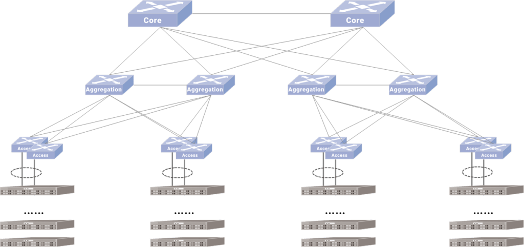
Networking Solution 1: MC-LAG At the Aggregation Layer :Through the cross-device port virtualization technology (MC-LAG), the network logic between the aggregation layer and the access layer switch is realized without looping, replacing STP. Compared with the traditional STP breakpoint protection, this design has a clearer logical topology and more efficient link utilization. For MC-LAG paired devices, the control plane and management plane are independent, and only the protocol plane is coupled. In theory, the reliability is higher than that of stacking. It also provides the ability to upgrade devices independently, bringing convenience to maintenance.
Networking Solution 2: Establishing MC-LAG at the Access Layer:The same MC-LAG technology is applicable to the application scenario where dual network cards of the server require active-active access. The server is dual-active connected to the two NICs to share the MAC. Dual NICs implement a flow-based load sharing strategy. Therefore, configure the port connected to the server as a member port of MC-LAG through MC-LAG, and the MAC and ARP entries of the two ports will be synchronized in real time.
What Are the Benefits of MC-LAG?
As a cross-device link aggregation technology, MLAG not only has the advantages of increasing bandwidth, improving link reliability, and load sharing, but also has the following advantages:
- Enables simpler network design: With MLAG, multiple switches can be treated as a single logical device, simplifying the network design and reducing management complexity.
- Provides faster failover and better network stability: MLAG provides rapid failover and increased network stability, reducing downtime and improving overall network performance.
- Offers more flexible deployment options: MLAG can be deployed at different layers of the network stack and is compatible with different devices from different vendors, making it a more flexible option than some other link aggregation technologies.
- Improves scalability: MLAG can improve the scalability of network links, allowing for the addition of more devices and increased bandwidth without sacrificing network performance.
Overall, MLAG is a powerful technology that offers a range of benefits for network optimization, including increased bandwidth, improved link reliability, load sharing, faster failover, and greater network stability. By providing a more flexible and scalable option for link aggregation, M-LAG can help organizations to build more efficient and reliable networks.
MC-LAG Configuration on Asterfusion Enterprise SONiC Distribution Switch
MC-LAG Configuration on Asterfusion Enterprise SONiC Distribution Switch
Related Products
-
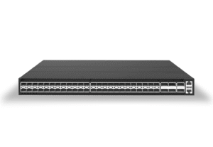 48x10Gb SFP+, 6x100Gb QSFP28 L3 Leaf & Core Switch, Enterprise SONiC Ready
 -
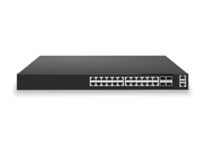 24x1G RJ45 L2/3 Access Switch, 4x25Gb/10Gb SFP28 Uplinks, Enterprise SONiC Ready
 -
 48x1G RJ45 L2/3 Access Switch, 6x25Gb/10Gb SFP28 Uplinks, Enterprise SONiC Ready
 -
 48 port 10GE SFP+L3 Ethernet Core & Aggregation Switch, Enterprise SONiC Ready


