Table of Contents
AI Inference Is Difficult to Optimize
In production-grade inference for large language models (LLMs), infrastructure teams often face a “two-pronged dilemma.” From the user experience perspective, the key requirement is fast, smooth generation and immediate responsiveness. From the perspective of operations and platform architecture teams, however, the core metrics are GPU compute utilization and service cost.
In traditional colocated or hybrid deployment architectures, these two goals are often in conflict. To guarantee service quality and meet SLOs, teams are forced to reserve a large amount of redundant hardware capacity. This directly leads to low GPU utilization and a sharp increase in CAPEX (capital expenditure).
Understanding Prefill and Decode in LLM Inference
To address the latency and resource contention issues described above, it is first necessary to understand how LLMs process inference requests. As discussed earlier in the section on KV Cache, the LLM inference workflow is now commonly divided into two stages: Prefill and Decode. Both stages are part of the same inference workflow, but they perform fundamentally different tasks and are subject to different performance requirements.
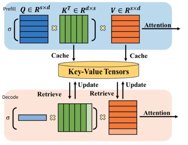
- Prefill: The Prefill stage processes the user’s input prompt and builds the initial context state, including the complete KV Cache required for subsequent token generation. It is a typical compute-intensive workload. Its performance directly affects Time to First Token (TTFT), which measures the time from when a user submits a request to when the first token appears. Long documents, extensive conversation history, and retrieval-augmented context windows all increase the Prefill workload, consuming more resources and increasing the user’s initial wait time.
- Decode: The Decode stage generates the response autoregressively. Based on the existing context state, the model generates response tokens one at a time while continuously reusing and updating the KV Cache. This stage is highly memory-bandwidth-intensive. Its performance directly affects Token Between Tokens (TBT), also commonly referred to as Time Per Output Token (TPOT). These metrics are key to the perceived smoothness of streamed output.
The two stages can be compared as follows:
| Performance Metric | Prefill Pool (P-Pool) | Decode Pool (D-Pool) |
| Core SLO Objective | TTFT (Time to First Token) | TPOT / TBT (Token-to-Token Latency and Output Smoothness) |
| Compute and Resource Bottleneck | Compute-bound | Memory-bound (HBM Capacity and Bandwidth) |
| Traffic Characteristics and Pattern | High-throughput bursts with long prompts and high concurrency | Continuous streaming of small responses with long-running stable batches |
| Hardware Selection Preference | Focus on high-performance Tensor Cores and high FLOPS | Focus on large GPU memory capacity and high HBM bandwidth |
However, there are currently two main approaches to deploying these two stages in the industry.
From Fused to Prefill-Decode Disaggregation
The industry has reached broad consensus that Prefill and Decode are the two main stages of LLM inference. However, two major approaches have emerged for scheduling and organizing these workloads: co-located (fused) and disaggregated.
This is more than a change in software scheduling. It also affects GPU resource allocation and the architecture of the underlying AI inference network.
Fused: Shared Resources for Higher Overall Utilization
In a fused architecture, Prefill and Decode run on the same GPU resources. Fine-grained scheduling allows the two stages to share compute resources and improve overall utilization.
One of the early representative works was Orca, presented at OSDI 2022, which introduced iteration-level scheduling. Later approaches, including Sarathi-Serve and FastGen, further explored Chunked Prefill. They split long Prefill sequences into smaller chunks and interleave them with Decode iterations.
The main advantage of the fused approach is higher GPU utilization. Decode is typically memory-bandwidth-bound, leaving some GPU compute resources underutilized. Scheduling Prefill workloads during this time can make better use of the available compute capacity. In addition, because Prefill and Decode run on the same GPUs, they can share data such as model weights, reducing redundant data reads.
However, this approach introduces an important limitation: the resource allocation and parallelism of Prefill and Decode are tied to the same resource pool.
For short prompts, Prefill requires relatively little compute time, and resource sharing can work well. However, as prompt length and context size increase, Prefill requires significantly more compute resources and execution time. Because both stages share the same GPU resource pool, the system cannot easily scale resources or adjust parallelism independently based on their workload characteristics.
As a result, Prefill and Decode may compete for GPU compute capacity, memory bandwidth, and other resources. This makes it difficult to optimize both TTFT and TPOT/TBT simultaneously. These limitations have driven the development of PD disaggregation.
Disaggregated: Independent Optimization for Different Workloads
As demand for long prompts and large context windows continues to grow, disaggregated approaches, represented by Splitwise and DistServe, further decouple Prefill from Decode. The two stages run in separate resource pools or nodes.
The core value of PD disaggregation is to reduce resource contention between the two stages. This allows Prefill and Decode to be optimized independently around their respective performance targets.
Prefill focuses more on compute capacity and TTFT. GPU resources and parallelism strategies can therefore be configured based on workload characteristics such as input length and request arrival rate.
Decode places greater emphasis on memory bandwidth, KV Cache capacity, batch size, and TPOT. Its GPU resources and parallelism strategy can be optimized for the characteristics of continuous token generation.
This decoupling also allows Prefill and Decode to scale independently. When long-prompt requests increase and Prefill resources become constrained, additional Prefill resources can be deployed without scaling the entire inference cluster. Similarly, Decode resources can scale independently as the number of concurrent generation requests increases.
PD disaggregation therefore removes the requirement for a uniform hardware configuration across the entire cluster. Resources can instead be matched to the actual workload of each stage. This reduces overprovisioning while meeting service SLOs, improving overall resource utilization, and lowering infrastructure cost per request and overall CAPEX.
A New Challenge: Cross-Node KV Cache Transfer
However, decoupling the resources also introduces a new system-level challenge.
In a fused architecture, Prefill and Decode run on the same compute resources. The handoff of context state occurs primarily within local resources. In a PD-disaggregated architecture, Prefill and Decode reside in separate resource pools. The KV Cache generated during Prefill must therefore be transferred across nodes to the Decode pool.
This changes KV Cache transfer from an interaction within local compute resources into an important network workload.
As the number of concurrent requests and context lengths increase, KV Cache transfers can consume substantial network bandwidth and generate significant burst traffic. When multiple Prefill instances complete processing at the same time, large volumes of KV Cache data may be sent to a limited number of Decode resources within a short period. This further increases the risk of network congestion and tail latency.
Therefore, while PD disaggregation addresses resource contention between Prefill and Decode, it also shifts part of the performance pressure to the network.
Asterfusion’s Approach: An Asymmetric Dual-Plane Network Architecture
In a PD-disaggregated environment, multiple Prefill nodes may complete processing at roughly the same time and concurrently transfer KV Cache data to the Decode node cluster.
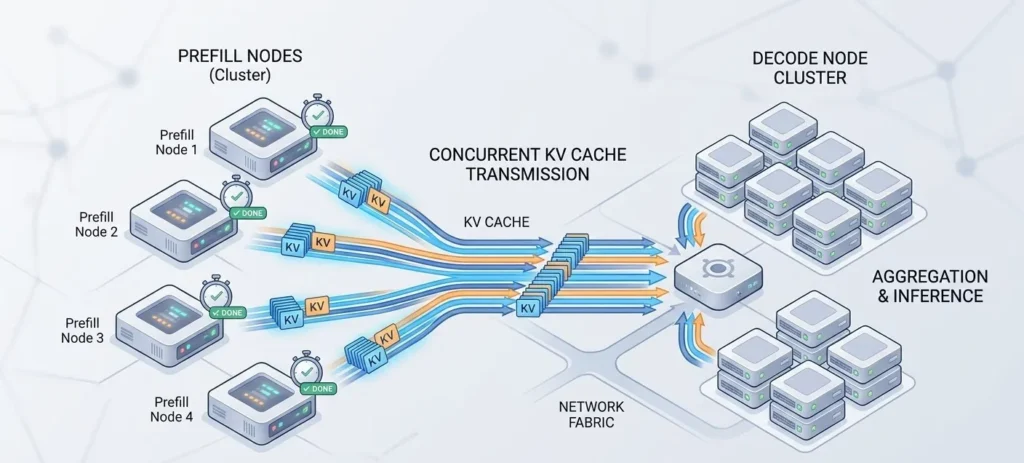
If the network design does not match the traffic model, multiple KV Cache transfers may converge on the same links and queues. This can trigger microbursts, queue congestion, PFC backpressure, and increased tail latency. Even if the Prefill stage has reduced TTFT, KV Cache transfer latency across the network can become a new performance bottleneck.
Therefore, PD disaggregation is not simply about placing Prefill and Decode in separate GPU resource pools. It also requires a new approach to the network architecture and traffic management between the two pools.
Asterfusion addresses this challenge at two levels. At the infrastructure level, the network is designed around the asymmetric characteristics of Prefill and Decode workloads. At the network level, congestion control, path selection, and QoS are optimized for the high-volume RoCEv2 traffic generated by KV Cache transfers.
An Asymmetric Dual-Plane Network for P-D Disaggregation
Traditional data center networks typically use a symmetric design. Both sides use a similar number of switches, port speeds, and oversubscription ratios. This approach works well when workloads and capacity requirements are relatively similar.
However, PD disaggregation is inherently asymmetric.
The Prefill and Decode pools may differ in GPU count, GPU specifications, traffic direction, traffic duration, and bandwidth requirements. The ratio of Prefill to Decode resources can also change with prompt length, request arrival rate, and generation workload.
Therefore, the network should not simply replicate infrastructure symmetrically. Network capacity, port speeds, and oversubscription ratios should instead be planned independently based on the actual P/D GPU ratio and traffic model.
Asterfusion’s Asymmetric Dual-Plane Network Architecture for PD disaggregation follows this principle. It moves network resource planning from a uniform configuration model to a workload-driven model.
By adjusting switch scale, port speeds, and oversubscription ratios for each plane, network capacity can better match the actual resource requirements of the Prefill and Decode pools. When the P/D ratio changes, the corresponding resource pool can also scale independently. There is no need to expand network infrastructure symmetrically.
This infrastructure-level optimization starts with network scale and topology. It reduces overprovisioning caused by building both sides for the worst-case scenario, helping lower the CAPEX of the AI inference fabric.
RoCEv2 Network Optimization for High-Volume KV Cache Traffic
The infrastructure architecture addresses how the network should be built. Network functions further address how KV Cache traffic should run efficiently across that network.
In a RoCEv2 network, KV Cache handoff is fundamentally RDMA traffic. The source is the NIC on the Prefill node, while the destination is the NIC on the Decode node. Because these transfers are typically high-volume and bursty, KV Cache does not require a new transport protocol. Existing traffic engineering and congestion control mechanisms in the AI fabric can be used instead, including QoS, ECN, PFC, and adaptive routing.
QoS, ECN, and PFC: Managing Congestion and Queue Pressure
When KV Cache transfers share network resources with other AI traffic, QoS can classify different traffic types and apply appropriate priority policies.
For RoCEv2 traffic, ECN uses congestion marking to provide network feedback to the sender, helping it reduce its transmission rate. PFC can pause traffic at a specific priority during congestion, helping prevent switch buffer overflow and RDMA packet loss.
With appropriate QoS policies, ECN thresholds, and PFC configuration, the impact of bursty KV Cache transfers on queues and tail latency can be reduced. These mechanisms also help maintain the low-loss transport environment required by RoCEv2 RDMA traffic.
Note: To learn more about Easy RoCE, refer to Asterfusion’s Asterfusion Easy RoCE: Enabling Lossless Ethernet with a Single Command Line.
ARS / Flowlet: Reducing Path Imbalance for Large Flows
For high-volume flows such as KV Cache transfers, traditional five-tuple ECMP hashing can lead to hash polarization. A small number of large flows may be pinned to a limited set of paths, causing localized congestion while other equal-cost paths still have substantial available bandwidth.
In a multipath AI fabric, Adaptive Routing or flowlet-based routing can further improve path utilization. These mechanisms dynamically select more suitable paths based on network or link conditions, allowing KV Cache traffic to be distributed more evenly across the fabric.
The goal is not simply to split large flows into smaller flows. It is to reduce path polarization and localized hotspots caused by a small number of large flows, allowing the available bandwidth of the multipath network to be used more effectively.
The asymmetric dual-plane architecture allows network capacity, oversubscription ratios, traffic priorities, and scaling strategies to be aligned with actual AI inference workloads rather than increasing hardware uniformly.
Asterfusion optimizes P-D disaggregation deployments from two dimensions: network infrastructure architecture and traffic scheduling and congestion control. The goal is to align network capacity, oversubscription ratios, traffic priorities, and scaling strategies with actual AI inference workloads instead of simply replicating symmetric infrastructure or blindly adding hardware.
If you want know more about symmetric dual-plane network design, see: AI Computing Fabric Dual-Plane Network Architecture Design
Designing the Network for Maximum Value
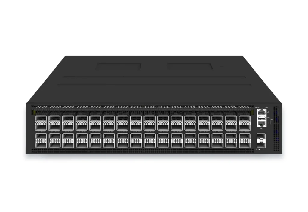
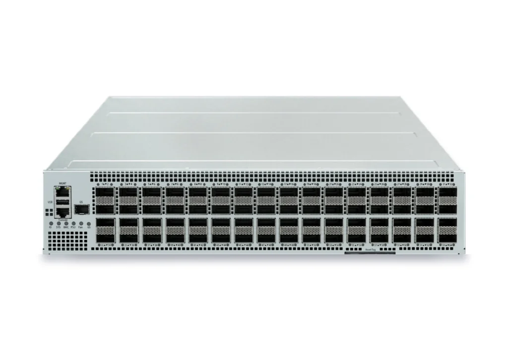
By designing an asymmetric network architecture for PD disaggregation and combining RoCEv2 traffic scheduling with QoS, ECN/PFC, and adaptive routing, Asterfusion can reduce overprovisioning of switches, optical transceivers, and network links while meeting network stability requirements.
Based on Asterfusion’s solution evaluation, under specific AI inference cluster sizes and workload models, a network architecture optimized for PD disaggregation can deliver around 30% CAPEX reduction across the overall AI inference fabric.
This cost optimization does not come simply from using fewer switches. It results from coordinated optimization across the network infrastructure, including switch scale, port speeds, optical transceivers, link count, and oversubscription ratios.
However, achieving these savings does not simply mean reducing network equipment. The key is to design the network around the actual characteristics of Prefill and Decode workloads.
So, how does Asterfusion design an asymmetric dual-plane network based on the workload characteristics of PD disaggregation? And how can network architecture and traffic scheduling work together to reduce infrastructure CAPEX by around 30% while maintaining AI inference performance?
Stay tuned for the detailed architecture !
Request a demo or need assistance ?
Fill out the form, and we’ll reach out to you today !


