Table of Contents
Introduction
In the past, broadcast systems relied on SDI (Serial Digital Interface) for signal transport.
Today, the industry is shifting to IP-based architectures for better flexibility, scalability, and higher resource utilization.
This transition is reshaping the fundamentals of production and playout workflows. PTP switches for broadcast are accelerating this shift.
In an IP environment, devices rely on the network and their local clocks to transmit and receive audio and video streams.
If time synchronization fails, issues such as audio-video misalignment, frame tearing, and switching glitches will occur. Accurate timing is essential for stable operation.
To address this, the industry adoptsIEEE 1588, or PTP. It provides nanosecond-level accuracy over Ethernet and aligns all devices to a common notion of absolute time. When deployed via PTP switches for broadcast, this ensures consistent synchronization across all endpoints. Under the SMPTE ST 2110 standard, PTP synchronizes all video and audio streams. Multi-camera and multi-format workflows remain as stable as traditional SDI, with even higher precision.
This is the foundation for reliable operation in mission-critical AV-over-IP systems.
Understanding Precision Time Protocol (PTP) Fundamentals
PTP: A Leap Beyond NTP
PTP is a high-precision time synchronization technology over Ethernet. It achieves nanosecond-level accuracy and is widely used in broadcast and telecom networks.
Compared to NTP, which typically operates at millisecond-level accuracy, PTP delivers a significant improvement in precision within LAN environments through hardware timestamping and precise message exchange.
PTP uses NIC-based hardware timestamping at the PHY layer. This minimizes software-induced jitter. With proper configuration, synchronization accuracy can be controlled within 10 nanoseconds.
The key difference between PTP and NTP is precision. PTP operates at the nanosecond level, while NTP typically ranges from microseconds to milliseconds.
Comparison: PTP (nanoseconds) vs. NTP (microseconds)
| Item | PTP (Precision Time Protocol) | NTP (Network Time Protocol) |
| Accuracy | Nanoseconds (ns) | Microseconds (µs) ~ milliseconds (ms) |
| Typical Use Case | Data center, 5G, finance, industrial control | General IT systems, servers, desktops |
| Time Precision Level | Very high (sub-microsecond) | Moderate |
| Protocol Standard | IEEE 1588 | RFC 5905 |
| Synchronization Method | Hardware timestamping (NIC / switch support) | Software timestamping |
| Network Dependency | Requires controlled network (low jitter, low latency) | Works over public or unmanaged networks |
| Complexity | High | Low |
| Deployment Cost | Higher (hardware support needed) | Very low |
| Traffic Sensitivity | Sensitive to delay variation (PDV) | More tolerant |
| Scalability | Limited by network design (hierarchical clock architecture) | Highly scalable (internet-wide) |
| Clock Hierarchy | Grandmaster → Boundary/Transparent Clock → Slave | Stratum levels (Stratum 0–15) |
| Hardware Support | Required for best accuracy | Not required |
| Typical Accuracy Range | < 100 ns (with hardware support) | 1 ms – 10 ms (typical internet) |
PTP is designed for high-precision environments requiring nanosecond-level synchronization, while NTP is suitable for general-purpose time synchronization with microsecond to millisecond accuracy. For broadcast environments, PTP switches for broadcast are typically used to achieve nanoseconds precision across the network.
How PTP Achieves Synchronization
PTP uses a master–slave clock architecture. It relies on periodic message exchange to measure clock offset and path delay, enabling continuous time correction.
The process works as follows. The master clock sends a Sync message and records the transmit timestamp t1. The slave records the receive timestamp t2. The master then sends a Follow_Up message carrying the precise t1. The slave sends a Delay_Req message at t3, and the master replies with a Delay_Resp message containing t4.
Based on these four timestamps, the slave computes the clock offset and one-way path delay, and adjusts its local clock accordingly.
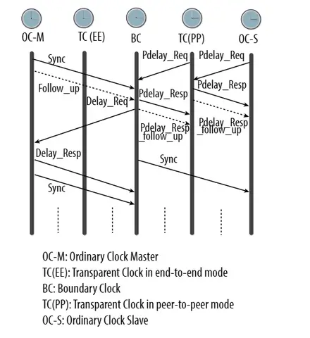
Key PTP Clock Types
Key clock types in a PTP network include the following.
The Grandmaster clock serves as the primary time reference. It is typically locked to UTC via GPS or an atomic clock, and is selected through the Best Master Clock Algorithm (BMCA).
An ordinary slave clock is usually an endpoint device, such as a camera or a switch. It synchronizes to the master and does not provide timing to other devices.
A boundary clock operates as an intermediate node. It behaves as a slave on upstream ports and as a master on downstream ports. This enables hierarchical scaling and improves timing stability across the network.
A transparent clock compensates for network-induced delay. In End-to-End mode, it accumulates residence time across each hop. In Peer-to-Peer mode, it also measures link delay dynamically. This ensures nanosecond-level accuracy over multi-hop paths.
PTP Profiles for Broadcast
For broadcast deployments, dedicated PTP profiles are defined to standardize key parameters. These profiles are also mandatory for PTP switches used in broadcast networks.
For example, SMPTE ST 2059-2:2023 is the primary profile for video and audio applications. It defines parameters such as Domain Number, Announce interval, Sync interval, and Delay Request interval to ensure sub-microsecond synchronization accuracy.
These parameters are tightly controlled. Domain isolation prevents PTP messages from interfering across systems. A long Sync interval increases clock drift, while a short interval adds bandwidth overhead. Broadcast deployments require strict compliance with the profile to maintain timing integrity.
For more details about PTP , see What is PTP and How does it Work?
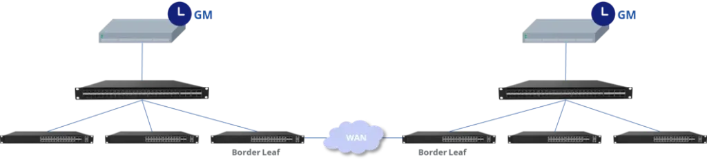
Best Practices for Deploying PTP Switches for Broadcast
Here’s a brief guide to deploying PTP Switches for Broadcast networks.
- Develop a Clear PTP Architecture Plan
- Define PTP Domain and Profiles
- Implement Grandmaster Redundancy (at least two)
- Strategically Deploy Boundary Clocks within the Network
- Choose the Right Grandmasters
- Look for GPS or GNSS Locking and Redundant Power
- Ensure Hitless Switching and ST 2110-10 Support
- Understand and Configure the Best Master Clock Algorithm (BMCA)
- Intentionally Set P1 and P2 Priorities
- Thoroughly Test Failover Behavior
- Protect PTP Packets with Robust Network Configuration
- Configure PTP switches for broadcast in Boundary Clock mode
- Avoid Congestion Points near Grandmasters and Boundary Clocks
- Implement Continuous PTP Monitoring
- Utilize Tools like Asteria OpenWiFi Controller or Switch Telemetry
- Monitor Key Metrics: Master-to-Slave Offset, Jitter, Announce Intervals, Leadership Changes, Sync, and Delay Measurements
- Validate in a Staging Environment
- Simulate Real-World Conditions: Grandmaster Failover, Congestion, Power Cycling, Link Loss
- Train Your Team
- Equip Staff to Identify Timing Faults, Read Logs, and Respond to GM Failovers
- Ensure Proficiency in Using Monitoring Tools
For more on PTP deployment scenarios, see PTP Design Best Practices for Media & Entertainment IP Networks
The Impact of Incorrect PTP Implementation
Improper PTP deployment can have critical consequences. In ST 2110 networks, this often appears as random glitches and overall system instability.
If the Grandmaster election fails, clocks across the network drift. A few hundred nanoseconds of drift may seem minor and often go unnoticed. However, if phase jumps reach the microsecond level, audio-video misalignment, frame tearing, or black frames can occur.
Standard switches without Boundary or Transparent Clock support accumulate residence delay, causing downstream signal misalignment. Inconsistent profile parameters—for example, one device using Domain 0 and another Domain 127—can completely break synchronization, resulting in black screens or dropped frames during camera switching.
These issues are magnified in live broadcast environments. Operations teams may spend weeks troubleshooting, only to find that a Sync interval was misconfigured by an order of magnitude. Such errors severely affect program quality and undermine customer trust.
Why 10ns PTP Switches for Broadcast Matters
All of the preceding discussion—PTP fundamentals, industry standards, best practices, and the risks of misdeployment—assumes the baseline use of PTP switches.
According to ST 2059-2, broadcast devices must achieve sub-microsecond synchronization. This is sufficient for normal playout. However, in complex IP production environments, extra precision margin is critical for system robustness.
For example, standard switches with ~100 ns accuracy can approach their limits under extreme conditions, such as temperature drift, network congestion, or master clock failover, potentially triggering synchronization alarms.
In contrast, 10 ns PTP switches for broadcast provide more than 100× precision margin. Even across multi-hop boundary clock chains or fluctuating link conditions, they keep endpoint devices locked within a stable synchronization window.
This is why 10 ns PTP switches for broadcast are a better choice. They not only meet the standard but also enhance reliability, raising the operational ceiling for IP-based broadcast systems.
Conclusion: Achieving Flawless Synchronization with PTP
The broadcast industry is moving from SDI to IP, with SMPTE ST 2110 and ST 2059 as core standards. PTP switches for broadcast are essential for frame-level audio-video synchronization and reliable IP production networks.
Without PTP switches for broadcast, devices cannot sync to the master clock, becoming isolated in the IP ecosystem. 10 ns PTP switches for broadcast meet ST 2059 requirements and perform better in multi-camera, multi-format workflows.
Hardware precision alone is not enough. Proper deployment is critical. Even high-precision PTP switches for broadcast can fail if misconfigured, causing audio-video misalignment or black frames. Only with correct planning and operations can PTP switches for broadcast ensure stable, mission-critical IP systems.
Other PTP Blogs You Should Read
- What is PTP and How does it Work?
- All PTP Clock Types and How to Configure in Asterfusion
- PTP Profiles for Network Engineers: How to Pick the Best Profile
- AV over IP Switches Enable Cost-Effective Live Streaming Networks
- How to Deploy PTP Synchronization in 5G Open RAN Small Cell Networks with a GNSS-Enabled Switch
- Why PTP Network Switches are Used in Financial Trading?
- PTP Design Best Practices for Media & Entertainment IP Networks
Real Case Study:
- SMPTE 2110 in IP-Based Broadcast Studio Design: A Transforming with Asterfusion
- Asterfusion PTP Switch Powers Live Streaming of Australia’s Premier Sporting Events
Have a project in mind?
Fill out the form, and we’ll reach out to you today !
Contact US !
- To request a proposal, send an E-Mail to bd@cloudswit.ch
- To receive timely and relevant information from Asterfusion, sign up at AsterNOS Community Portal
- To submit a case, visit Support Portal
- To find user manuals for a specific command or scenario, access AsterNOS Documentation
- To find a product or product family, visit Asterfusion-cloudswit.ch


