Table of Contents
As professional audio and video systems move toward IP-based networks, Ethernet switches need to deliver precise time synchronization, predictable latency, and reliable bandwidth management. Asterfusion AVB Ethernet Switches (CX102s Series) combine IEEE 802.1AS time synchronization, IEEE 802.1Qat stream reservation, and IEEE 802.1Qav traffic shaping to support real-time audio and video transport. The series offers flexible port configurations, including 8 × 1G RJ45, 8 × 2.5G RJ45, and 16 × 1G RJ45, each with 2 × 10G optical uplinks, providing flexible connectivity for professional AV networks.
1. From Traditional SDI to Ethernet-Based AV Networks
Imagine a large television broadcasting studio, a live production venue, a conference center, or a concert hall.Behind the scenes, dozens or even hundreds of devices work together to deliver audio and video content. Cameras capture video, microphones collect audio, digital signal processors (DSPs) process signals, mixing consoles manage audio, and speakers and displays deliver the final output.All these devices need to exchange audio and video signals reliably, often in real time.Traditionally, this has been achieved using SDI (Serial Digital Interface), a technology widely used in professional broadcasting and video production.
In a traditional SDI system, each connection typically uses a dedicated coaxial cable with BNC connectors to carry a video signal between devices. Dedicated SDI routers manage signal switching and distribution. This architecture has proven reliable for many years. However, as video resolutions increase and production environments become more complex, its limitations are becoming increasingly apparent.
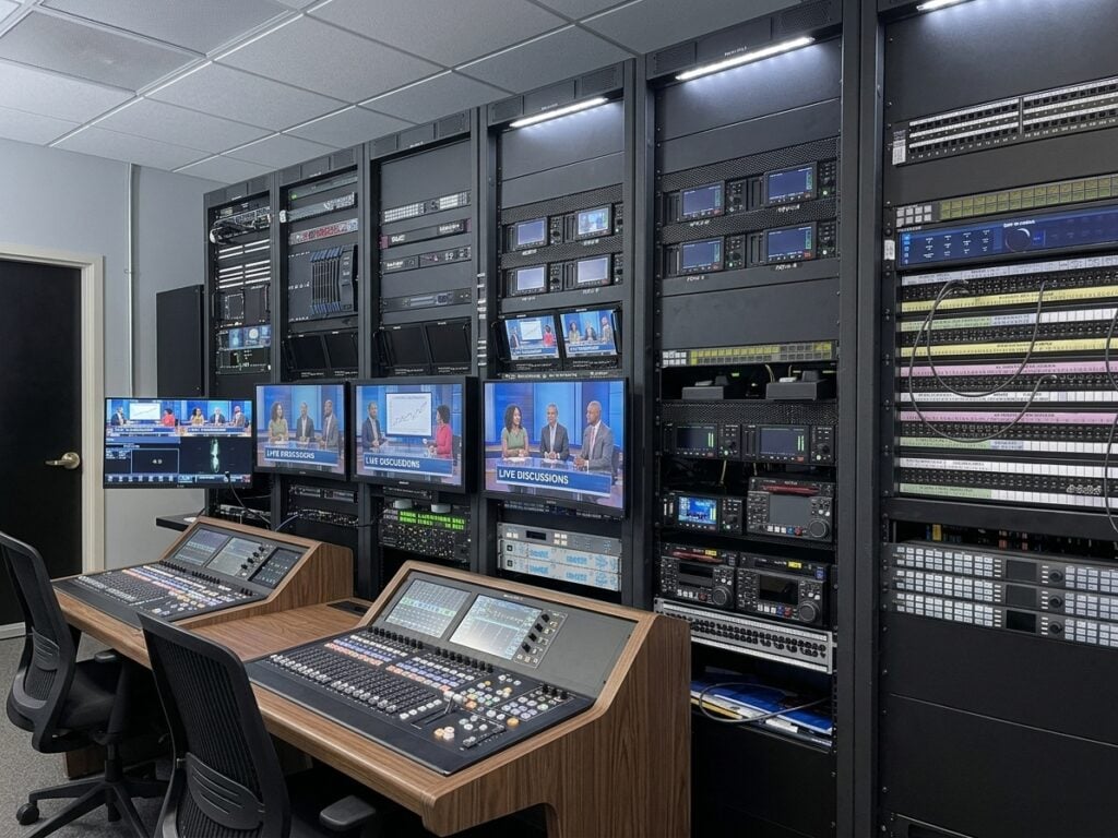
- The first challenge is cabling and port consumption:Each SDI link typically carries one unidirectional signal. As video bandwidth requirements grow, multiple links may be needed to transport a single video feed. For example, transmitting 8K 60p video with 10-bit 4:2:2 sampling using Quad-link 12G-SDI requires four separate links for one complete video signal. This significantly increases cable quantities, router port usage, and connection management complexity.
- The second challenge is infrastructure upgrades:Moving from HD-SDI to 3G-SDI, 6G-SDI, or 12G-SDI requires careful evaluation of cable quality, transmission distance, connectors, and signal integrity. Existing cabling that works reliably for HD-SDI cannot automatically be assumed to support higher data rates.
- The third challenge is limited flexibility in signal distribution:Audio and video are often embedded together in an SDI signal. When they need to follow different processing paths, additional equipment may be required to separate audio from video and embed the processed audio back into the signal.
Finally, expanding an SDI-based system often means adding more dedicated cables, interfaces, and routing resources. As the number of devices grows, managing physical connections and signal paths becomes increasingly complicated. These challenges raise an important question: Can audio and video signals be transported over a shared Ethernet network instead of relying on dedicated point-to-point SDI connections?
This is where Ethernet-based AV networking comes in.
2. Why Move Audio and Video to Ethernet?
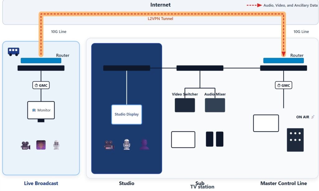
Ethernet offers a fundamentally different approach to media distribution. Instead of assigning a dedicated physical connection to every signal, multiple audio and video streams can travel across shared network links. Ethernet switches forward these streams to their intended destinations, allowing compatible devices to communicate through a common network infrastructure. Compared with traditional SDI infrastructure, Ethernet-based AV networking offers several advantages:
- Shared Infrastructure: Multiple media streams can use the same Ethernet links, reducing the need for dedicated point-to-point cabling.
- Flexible Distribution: Ethernet switches allow media streams to be distributed to different endpoints through a switched network.
- Simplified Expansion: Additional compatible devices can be integrated into the network without requiring an entirely separate physical connection for every signal.
- Better Resource Utilization: Available network bandwidth can be shared among multiple streams according to their transmission requirements.
However, there is an important distinction: Ordinary Ethernet connectivity does not automatically guarantee reliable real-time audio and video transmission. Conventional Ethernet uses a Best-Effort forwarding model. When multiple traffic streams compete for network resources, congestion can introduce variable latency, packet loss, and unpredictable delivery times. For ordinary file transfers, these variations are often acceptable. For real-time audio and video production, they can create serious problems.
Consider a live production environment:Audio must arrive in time for playback,video streams must be delivered without disruptive interruptions,multiple speakers must play audio in synchronization,audio and video must be presented at the correct time……Simply connecting AV devices to an Ethernet switch is therefore not enough. The network must also provide time synchronization, bandwidth assurance, and controlled traffic scheduling.
This is exactly what Audio Video Bridging (AVB) is designed to address.
3. What Is AVB (Audio Video Bridging)?
Audio Video Bridging (AVB) is a family of IEEE standards that enables real-time audio and video transmission over Ethernet networks. It extends conventional Ethernet with mechanisms for precise time synchronization, bandwidth reservation, and controlled traffic scheduling, allowing multiple media streams to share the same network while maintaining predictable delivery. Unlike traditional SDI systems, which rely on dedicated connections for individual signals, AVB allows audio and video devices to communicate through a shared Ethernet switching infrastructure. This makes it easier to distribute media streams between devices, expand production systems, and share network resources.
4. How Does an Audio Video Bridging Network Work?
A typical AVB network consists of three main components: Talkers, Listeners, and AVB Bridges. Each plays a specific role in transmitting and receiving media streams.
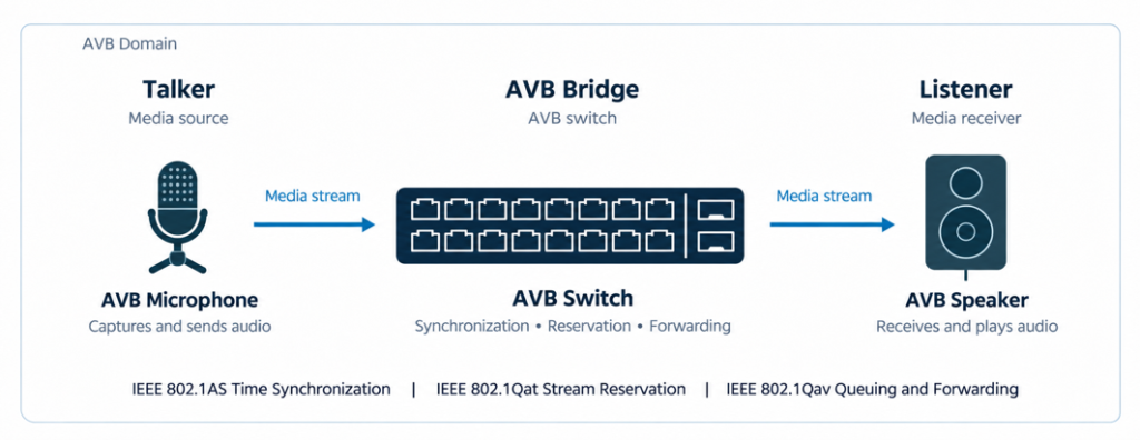
- Talker: A device that generates and transmits an audio or video stream. Examples include stage boxes, network-enabled microphones, cameras, and other AV endpoints.
- Listener: A device that receives an AV stream. Examples include audio processors, amplifiers, displays, and mixing consoles.
- AVB Bridge: An AVB-capable Ethernet switch that connects Talkers and Listeners. It participates in time synchronization, stream reservation, and traffic management to ensure that media streams are forwarded according to their requirements.
Not every audio device can connect directly to an AVB network. Traditional analog microphones and loudspeakers need an AVB-capable digital signal processor (DSP) or audio I/O device to interface with the network. For example, when a microphone captures sound, an audio I/O device converts the analog signal into digital audio and sends it across the Ethernet network as a Talker. At the receiving end, an AVB-enabled DSP or audio device acts as a Listener, receives the stream, processes or converts the audio, and delivers it to the loudspeaker.
In this way, AVB connects different audio and video devices through a common network, rather than requiring a dedicated physical connection for every media signal.
5. How Does AVB Ensure Reliable Real-Time Media Transport?
AVB (Audio Video Bridging) enables reliable, time-sensitive audio and video transport over Ethernet through three complementary mechanisms: time synchronization, bandwidth reservation, and traffic shaping. These functions are defined by key IEEE standards, including IEEE 802.1AS, IEEE 802.1Qat, and IEEE 802.1Qav. Together, they help AVB networks coordinate media playback, reserve the resources required by each stream, and control packet transmission to reduce congestion and unpredictable delays.
5.1 AVB Time Synchronization with IEEE 802.1AS
IEEE 802.1AS provides the timing foundation for an AVB network. Based on the generalized Precision Time Protocol (gPTP), it establishes a common time reference across AV endpoints and time-aware Ethernet bridges.
In a typical AVB network, devices first exchange clock information through Announce messages. The Best Master Clock Algorithm (BMCA) uses this information to select the Grandmaster Clock (GM), which becomes the network’s primary time reference. The participating devices then establish a synchronization hierarchy to distribute the GM’s time throughout the network.
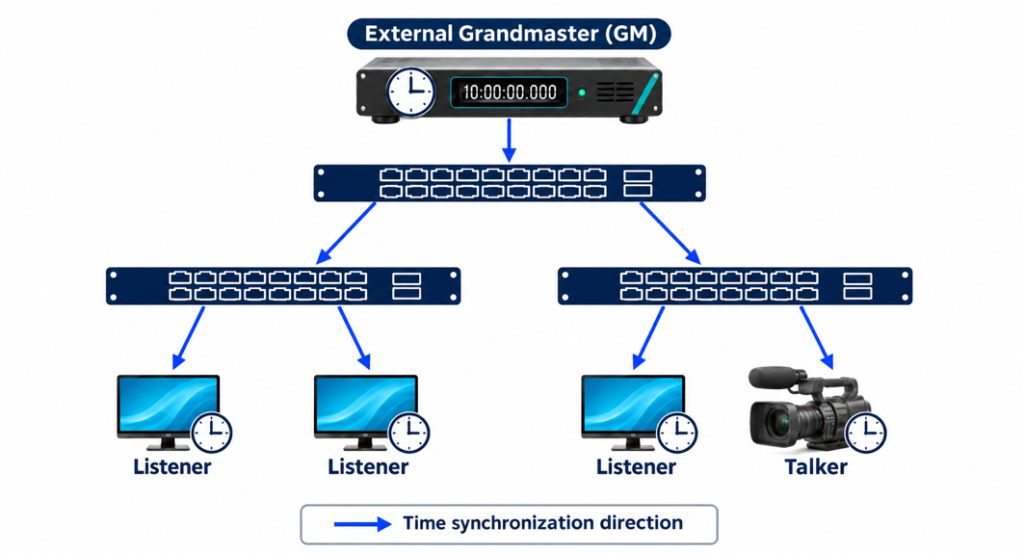
To maintain accurate synchronization, adjacent devices periodically exchange three types of peer delay messages:
- Pdelay_Req
- Pdelay_Resp
- Pdelay_Resp_Follow_Up
These exchanges allow devices to measure mean link propagation delay and determine the neighbor rate ratio. As timing information passes through the network, each time-aware bridge accounts for link propagation delay, bridge residence time, and clock rate differences. This hop-by-hop measurement and compensation process allows AV endpoints to maintain a synchronized clock aligned with the Grandmaster.
Why does this matter for AVB audio and video?
With a shared network clock, Talkers and Listeners can use media timestamps to coordinate playback. A Listener buffers media packets that arrive ahead of schedule and presents them at the specified network time. In other words, playback is determined by the synchronized presentation timestamp rather than the exact moment a packet arrives. This helps prevent timing variations from disrupting media presentation and enables synchronized loudspeaker output and coordinated audio-video playback.
5.2 AVB Bandwidth Reservation and Admission Control with MSRP (IEEE 802.1Qat)
Time synchronization alone is not enough for reliable AV transport. An AVB network must also ensure that sufficient bandwidth and forwarding resources are available before admitting a media stream.
The Multiple Stream Reservation Protocol (MSRP), originally defined in IEEE 802.1Qat, provides bandwidth reservation and admission control. It allows Talkers, Listeners, and AVB bridges to exchange stream declarations, check network resources, and establish reservations without requiring every device to be configured individually.
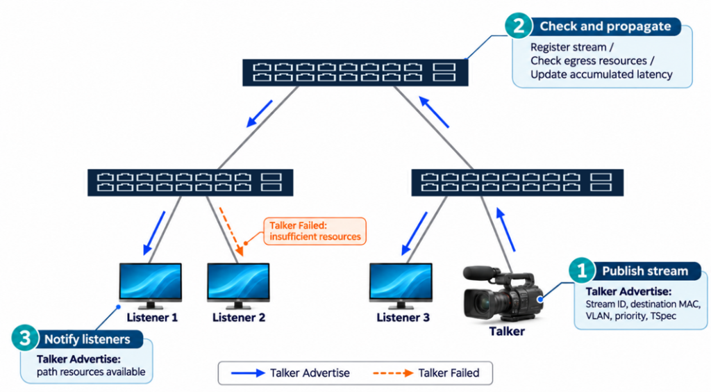
How does MSRP reserve bandwidth for an AVB stream?
MSRP uses two main Talker declaration types:
- Talker Advertise: Announces an available stream and indicates that no resource constraint has been identified along the advertisement path to the current device.
- Talker Failed: Reports that a resource shortage or another constraint has prevented the stream from being advertised successfully along a path.
A Talker Advertise declaration carries the information required for bridges and Listeners to evaluate the stream:
| Parameter | Purpose |
| Stream ID | Uniquely identifies the media stream |
| Destination MAC Address and VLAN ID | Identifies the stream destination, typically a multicast address, and its VLAN |
| Priority and Rank | Specifies traffic priority and reservation ranking |
| Traffic Specification (TSpec) | Defines the maximum frame size and maximum number of frames per measurement interval for bandwidth calculation |
| Accumulated Latency | Carries cumulative path latency information for Listener evaluation |
The reservation process takes place hop by hop:
- The Talker advertises the stream. It originates a Talker Advertise declaration containing the stream parameters and sends it to the adjacent AVB bridge.
- Each bridge checks available resources. The bridge registers the stream information, checks bandwidth and other resources on the relevant egress ports against the TSpec, and updates Accumulated Latency. If the checks pass, it forwards Talker Advertise downstream. If a resource constraint is detected, it propagates Talker Failed along the affected path, including the failure reason and the identity of the reporting bridge.
- The Listener evaluates the advertised path. A Listener uses the declarations to determine whether the stream is available and whether the advertised path can meet its requirements. A successful Talker Advertise allows the Listener to request the stream; Talker Failed indicates a constraint along the path.
How do Listeners request an AVB stream?
After receiving stream advertisements, Listeners send their own declarations toward the Talker. These declarations identify the requested stream through its Stream ID and propagate hop by hop along the path established by the Talker declarations.
MSRP uses three Listener declaration outcomes:
- Listener Ready: One or more Listeners request the stream, and all reception paths represented by the declaration have sufficient resources.
- Listener Asking Failed: One or more Listeners request the stream, but none of the represented reception paths meets the resource requirements.
- Listener Ready Failed: The aggregated declaration represents both at least one Listener with a successful reservation path and at least one Listener whose path cannot support reception.
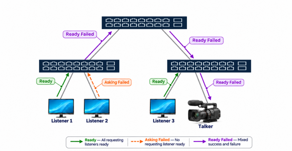
When a reservation succeeds, the bridges establish the required Layer 2 multicast forwarding state. This allows the reserved media stream to be forwarded from the Talker to the subscribed Listeners. By checking resource availability before admitting streams, MSRP helps prevent reserved AV traffic from exceeding the network capacity available along its path.
5.3 AVB Traffic Shaping and Low-Latency Transport with IEEE 802.1Qav
After synchronization and bandwidth reservation, the network must control how media packets are transmitted. IEEE 802.1Qav defines forwarding and queuing enhancements for AVB traffic, including the treatment of Stream Reservation (SR) classes and traffic shaping for time-sensitive media streams.
An AVB bridge typically handles traffic in several categories:
- SR Class A: The higher-priority reserved media class, with a typical worst-case network latency target of 2 ms over seven hops under specified operating conditions.
- SR Class B: A reserved media class below Class A, with a typical worst-case network latency target of 50 ms over seven hops under specified operating conditions.
- Control Traffic: Protocol traffic such as gPTP and MSRP, which supports time synchronization and bandwidth reservation and requires appropriate priority treatment.
- Best-Effort Traffic: Ordinary non-reserved traffic that uses the remaining transmission opportunities.
The exact queue mapping and control-traffic priorities depend on the applicable AVB profile and device configuration.
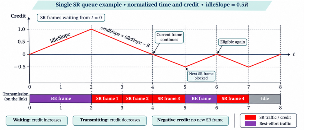
5.4 How does the Credit-Based Shaper (CBS) work?
IEEE 802.1Qav uses a Credit-Based Shaper (CBS) to regulate the transmission of SR-class traffic. Each SR queue maintains a credit value that determines when it is eligible to transmit. The mechanism works as follows:
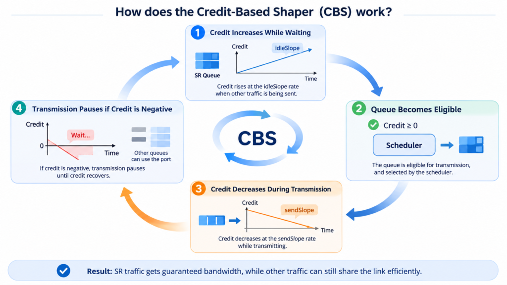
- Credit increases while waiting. When an SR queue has frames waiting but the port is transmitting other traffic, its credit increases at the idleSlope rate. The idleSlope corresponds to the bandwidth allocated to that queue.
- The queue becomes eligible to transmit. When its credit is non-negative, the queue is eligible for transmission. The egress scheduler then selects traffic according to priority and port availability.
- Credit decreases during transmission. While the SR queue is transmitting, its credit decreases at the sendSlope rate:
sendSlope = idleSlope − port transmit rate- Transmission pauses when credit becomes negative. If the credit is negative at the end of a frame transmission, the queue must wait while its credit recovers at the idleSlope rate. During this interval, other eligible queues can use the port.
By regulating when SR traffic can transmit, CBS limits consecutive bursts from reserved media queues and helps control queuing behavior. This makes bandwidth sharing more predictable while allowing other traffic classes to use available transmission opportunities.
6. How the Three AVB Mechanisms Work Together
IEEE 802.1AS, IEEE 802.1Qat, and IEEE 802.1Qav address three different requirements of real-time media transport:
| IEEE Standard | Core Function | Key Question |
| IEEE 802.1AS | Time Synchronization | When should media be presented? |
| IEEE 802.1Qat | Bandwidth Reservation and Admission Control | Is sufficient network capacity available? |
| IEEE 802.1Qav | Traffic Shaping and Queuing | How should media packets be scheduled for transmission? |
7. What Are the Benefits of AVB?
By combining these mechanisms, AVB offers several advantages for broadcast and professional AV networks.
- Simpler cabling: Multiple media streams can share an Ethernet link and be distributed through the switched network. Where link capacity is sufficient, this reduces dedicated cables and interfaces and simplifies system expansion.
- Dynamic resource reservation: Stream reservation checks, allocates, and releases bandwidth along the media path. Associated VLAN registration mechanisms maintain VLAN membership on relevant ports, reducing manual configuration and allowing media connections to adapt to operational needs.
- Synchronized presentation: gPTP establishes a precise common time reference. Combined with media presentation timestamps, it allows Listeners to output media at the intended time, supporting audio-video synchronization and coordinated playback across devices.
- Bounded transport latency: Bandwidth reservation and credit-based shaping control congestion and queuing delay. In a typical seven-hop network that meets the applicable link-rate, topology, and traffic requirements, Class A streams can achieve a network transit latency of 2 ms or less, supporting real-time production, monitoring, and sound reinforcement.
AVB transforms Ethernet from a general-purpose data network into a shared infrastructure capable of supporting synchronized, bandwidth-managed, and low-latency audio and video transport.
In our next articel, we’ll take a closer look at Asterfusion’s AVB Ethernet Switches powered by Enterprise SONiC. Stay tuned for more!


