Table of Contents
Introduction
In today’s rapidly evolving data center networks, the traditional three-tier access–aggregation–core architecture is no longer favored. Modern large-scale data centers primarily adopt CLOS architecture as their network fabric.
Why did this shift occur? The key reason is the change in traffic patterns. In the past, external users accessed web services by traversing the firewall, core, aggregation, and access layers to reach servers, then returning along the same path. This traffic model is known as north–south traffic and fits well with a clearly layered, hierarchical three-tier architecture.
Today, east–west traffic dominates. A single front-end request may trigger interactions among dozens of backend services, including database access, cache reads, and service-to-service calls. Virtual machine migration within a data center involves data movement between physical servers. Distributed computing workloads also rely heavily on east–west communication.
In a traditional three-tier network, traffic from a server must travel back to the aggregation or even the core layer to complete a data exchange. This results in significant bandwidth inefficiency and unnecessary latency. In contrast, a CLOS architecture eliminates STP and uses Layer 3 routing across the entire fabric. Traffic can be exchanged directly at the leaf layer. This is the primary reason CLOS has become the de facto standard.
This article introduces the evolution of the CLOS architecture, explains why CLOS is used, and discusses how Asterfusion’s enterprise SONiC and the TIP-based Asteria OpenWiFi Controller can be used to identify and implement a CLOS-based network.
CLOS Architecture in Telephone Networks
To understand the significance of the CLOS architecture, we need to go back to telephone networks in the 1950s.
Before Charles Clos proposed the CLOS theory, telephone switching systems mainly relied on devices known as crossbar switches. The concept was straightforward. As shown in the figure, a crossbar switch can be viewed as a large grid: horizontal lines represent input circuits, vertical lines represent output circuits, and each intersection requires a physical switch (relay).

This design was indeed simple, but it suffered from a fundamental limitation. As the number of users increased, the required number of crosspoints grew quadratically (N × N).
For example, connecting 100 users requires 100², or 10,000 crosspoints. Connecting 1,000 users requires 1,000,000 crosspoints. The resulting cost, physical space, and failure risk were all substantial.
Against this background, mathematician Charles Clos proposed a revolutionary multistage switching architecture in 1953. He demonstrated that a large single-stage switching matrix could be decomposed into three smaller cascaded stages: ingress, middle, and egress. This approach significantly reduces the number of physical crosspoints while still guaranteeing the network’s non-blocking property.
Non-blocking means that as long as the input and output ports are both idle, the network can always find a path to establish a connection.
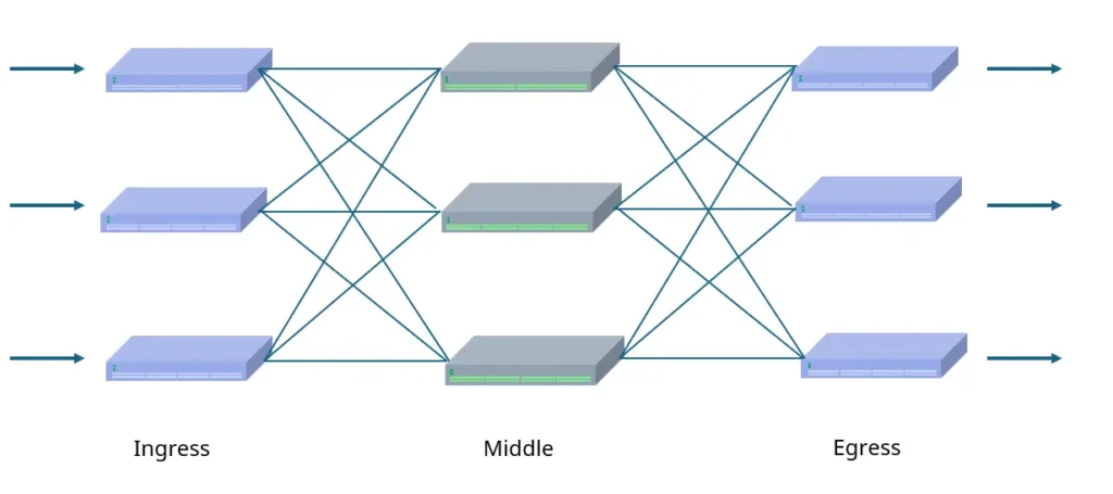
In a CLOS architecture, traffic, at that time, analog voice signals, enters through ingress switches, is routed across a set of switches in the middle stage, and finally exits through egress switches.
This design breaks the N × N limitation. It removes the need for expensive switching facilities and makes it possible to build large-scale, low-cost, non-blocking telephone networks.
With advances in electronic technology, electromechanical switches were later replaced by time-division multiplexing digital switches. As a result, the CLOS design appeared to fall out of use for a period of time. However, its core mathematical principle—achieving horizontal scalability through multistage interconnection—laid the foundation for the traffic explosion in the Internet era.
CLOS Architecture in Ethernet
In the early 2000s, with the rise of the Internet and cloud computing, traffic patterns in data centers began to change.
As discussed earlier, traditional enterprise networks typically used a three-tier access–aggregation–core architecture. This tree-like structure was well suited for north–south traffic. However, with the adoption of virtualization, distributed storage, and later AI workloads, east–west traffic between servers became dominant.
At this point, the CLOS architecture gained new relevance. The emergence of high-performance merchant silicon switch chips removed the need for expensive proprietary chassis systems. Networks could instead be built from large numbers of low-cost, standardized fixed-form-factor switches. As a result, the CLOS approach was revived in Ethernet and evolved into what is now known as folded Clos, or the leaf–spine architecture.
In data centers, the classic three-stage CLOS structure is “folded” along its vertical centerline and rotated by 90 degrees, forming the modern leaf–spine topology.
The original ingress and egress stages are merged into leaf switches that connect directly to servers. These are commonly referred to as top-of-rack (ToR) switches, with high port density on the server-facing side. The middle stage evolves into spine switches, which are typically high-performance devices with many high-speed ports and connect only to leaf switches.
The key property of this architecture is full connectivity between leaf and spine switches. This ensures that the hop count between any two servers is fixed and predictable.

Using a three-layer forwarding fabric based on a Clos topology, the network core runs Layer 3 routing protocols such as OSPF, IS-IS, or BGP, combined with equal-cost multipath (ECMP). This allows a leaf switch to reach any destination prefix through multiple spines using equal shortest paths.
With this design, modular scalability becomes highly attractive. To connect more servers, additional leaf switches can be added. If inter-server bandwidth is insufficient, additional spine switches can be deployed.
Note: Leaf–spine, folded Clos, and fat-tree are often used interchangeably, but they emphasize different aspects.
Originating from Charles Clos’s multistage switching theory, the folded Clos architecture is formed by physically folding and merging the originally separate ingress and egress stages. Leaf–spine is the most common engineering implementation of folded Clos. It clearly defines the physical layering of leaf access and spine interconnection. Fat-tree, by contrast, refers more to a design goal or topological concept. It aims to increase link capacity toward the upper layers, making bandwidth “fatter” as it moves upward, thereby eliminating blocking bottlenecks.
In simple terms, folded Clos describes the logical structure, leaf–spine is the physical implementation, and fat-tree represents a performance objective that ensures sufficient uplink bandwidth.
CLOS Architecture: From Three Tiers to Five and Seven Tiers
When a data center grows beyond the physical limits of a single leaf–spine fabric, the modular advantages of the CLOS architecture become fully apparent.
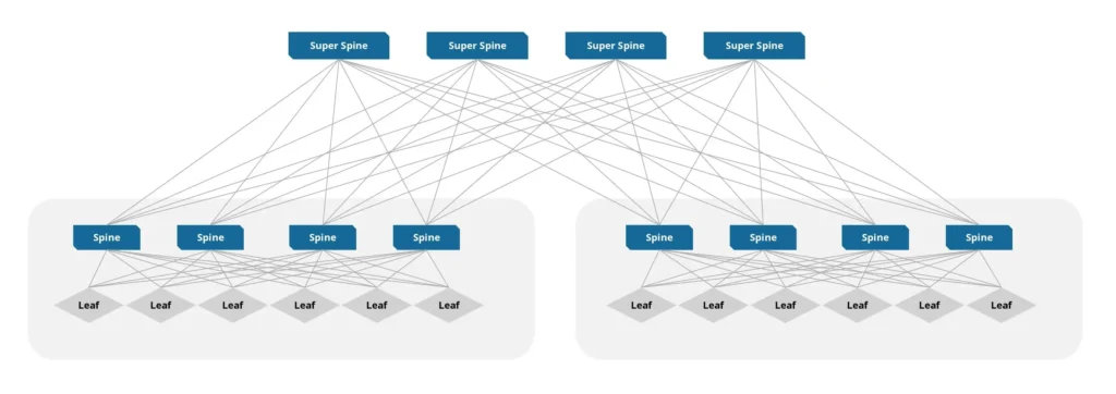
The well-known three-stage CLOS architecture, which is commonly implemented as a two-tier physical leaf–spine topology, is efficient but constrained by the port density of spine switches. Once all spine ports are consumed, no additional leaf switches can be connected. To address this limitation, the existing network does not need to be redesigned. Instead, a new layer can be introduced: the super-spine, also known as the super core. This expands the network from three stages to five stages.
The core idea behind this expansion is a pod-based design. In a five-stage architecture, all leaf and spine switches are no longer treated as a single large fabric. Instead, a group of leaf switches and their associated spine switches are packaged into an independent unit called a pod. Within each pod, the standard fully connected three-stage structure is preserved. The key change is that the spine switches inside a pod are no longer the top of the network. They dedicate a portion of their uplink ports to connect northbound to the newly introduced physical layer: the super-spine switches.
Under this architecture, traffic paths become deeper but remain well defined. As shown in the figure, packets originate from the source server, pass through the source leaf, reach the source pod’s spine, and are then forwarded upward to the globally shared super-spine layer. From there, traffic crosses pods to the destination pod’s spine and finally descends to the destination leaf. This results in a path of Leaf → Spine → Super-Spine → Spine → Leaf, which forms a logical five-stage switching fabric.
By the same logic, if the scale continues to grow, an additional layer can be added above the super-spine to build a seven-stage CLOS network. As long as the number of stages remains odd, the symmetry of this folded-and-expanded design can maintain non-blocking connectivity.
Why Use CLOS Architecture ?
The CLOS (leaf–spine) architecture has become the de facto standard for modern data centers and AI networks. Its key advantages include the following.
1. Modular horizontal scalability CLOS removes the physical limitations of traditional networks. Capacity can be expanded in a building-block manner. Add leaf switches to connect more servers. Add spine switches to increase aggregate bandwidth. This model allows the network to scale smoothly from dozens to tens of thousands of servers while maintaining a fully connected topology, without redesigning the entire fabric.
2. High performance and path redundancy The architecture provides non-blocking, full-bisection bandwidth by design. The communication distance between any two servers is fixed at three hops, ensuring low latency and predictable performance. Full mesh connectivity between leaf and spine switches creates multiple parallel paths and eliminates single points of failure. If a link or device fails, traffic is automatically redirected to alternate paths, providing high availability without service impact.
3. Efficient load balancing By using equal-cost multipath (ECMP), the CLOS architecture distributes traffic across all available physical links through hashing. This avoids the common issue of congested links alongside idle ones and ensures efficient utilization of all bandwidth resources. It is especially effective for bursty, high-throughput workloads such as AI training.
4. Simplified operations and automation The entire network follows a consistent leaf–spine topology with a regular, predictable structure. This significantly reduces operational complexity and provides a solid foundation for SDN and automated deployment workflows. At scale, network management becomes closer to managing a single logical system rather than thousands of individual devices.
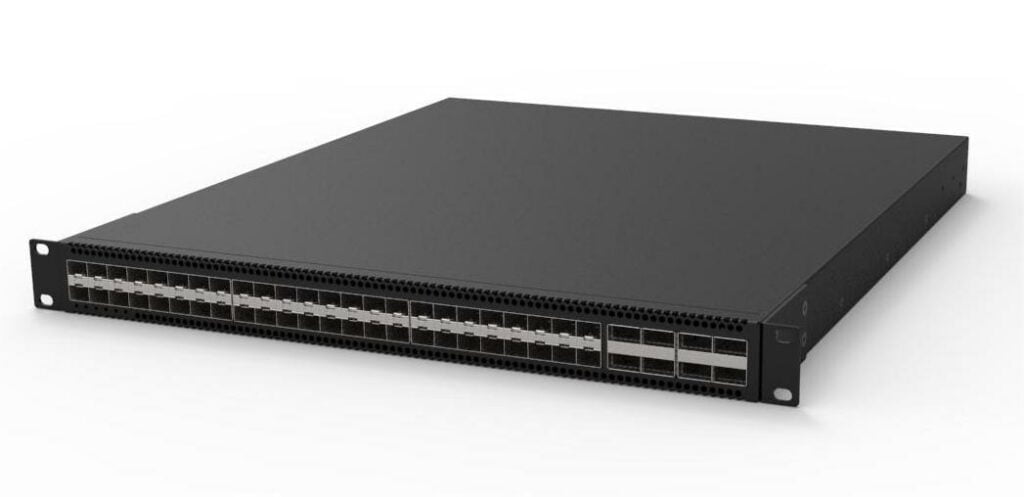
5. Cost efficiency and future readiness CLOS replaces expensive, closed chassis-based core switches with cost-effective, standardized 1U fixed-form-factor switches. The decoupling of the leaf and spine layers allows each layer to be upgraded independently. This flexibility extends the lifecycle of the network and makes it easier to adopt future technologies.
How Asterfusion Enterprise SONiC Enable CLOS Architecture
Asterfusion Enterprise SONiC, combined with the Asteria OpenWiFi Controller, provides an integrated management architecture that brings together software, visualization, and hardware.
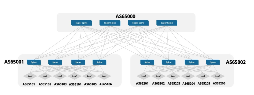
At the software layer, the underlay uses OSPF or an EBGP-based design that follows RFC 7938 for fabric-wide routing. On top of this, the overlay leverages VXLAN with BGP EVPN to deliver network virtualization and control.
The system supports the core BGP EVPN standards and provides fine-grained control-plane capabilities through the following route types:
- Type 1 (Ethernet Auto-Discovery): Fast convergence and active–active multihoming support
- Type 2 (MAC/IP Advertisement): Precise host reachability advertisement
- Type 3 (Inclusive Multicast): Automatic handling of BUM traffic
- Type 4 (Ethernet Segment Route): Redundancy for multihoming scenarios
- Type 5 (IP Prefix Advertisement): Distributed gateway and IP route propagation
With advanced suppression mechanisms such as ARP-to-Host, the entire fabric operates as a Layer 3 network. This reduces the impact of broadcast storms and significantly improves overall network stability.
Using the Asteria OpenWiFi Controller, network operations can be performed clearly through a web-based UI. This includes, but is not limited to, configuration deployment, clear visibility into network topology, monitoring of port status anomalies, and detailed insight into endpoint devices.
From both an architectural and hardware perspective, Asterfusion extends the CLOS architecture beyond chassis-based switches and beyond the data center itself. The same architecture is applied to campus networks, enabling architectural consistency across environments. The hardware portfolio spans from data center access-layer ToR (leaf) switches to core backbone spine switches, as well as from campus access devices to core-layer platforms. This allows enterprises to build a unified, high-performance leaf–spine network from the campus to the cloud.


Contact US !
- To request a proposal, send an E-Mail to bd@cloudswit.ch
- To receive timely and relevant information from Asterfusion, sign up at AsterNOS Community Portal
- To submit a case, visit Support Portal
- To find user manuals for a specific command or scenario, access AsterNOS Documentation
- To find a product or product family, visit Asterfusion-cloudswit.ch


