Table of Contents
Introduction
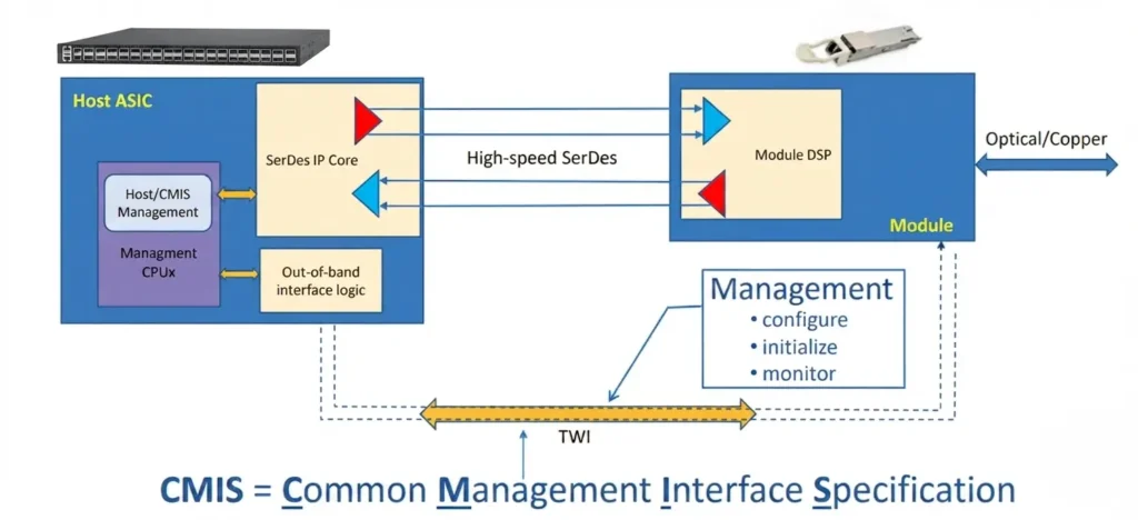
In modern AI data centers, network bandwidth is evolving from 400G to 800G and 1.6T. This rapid growth has introduced complex compatibility issues across optical modules from different vendors and various speed specifications. The legacy SFF interface specifications no longer meet the demands of complex 800G networks. Consequently, the Common Management Interface Specification (CMIS) has become essential. CMIS is more than a rigid technical standard; it serves as a universal language between optical modules and switches in high-performance data centers, particularly within AIDC architectures.
This article explores the fundamentals of CMIS and shares practical experience in managing optical modules using CMIS on Asterfusion data center switches.
What is CMIS?
Early optical module development relied on the SFF (Small Form Factor) family of standards. Key milestones include:
- SFF-8472: The standard for the SFP/SFP+ era, it enabled Digital Diagnostic Monitoring (DDM). It used the I2C interface to retrieve voltage, temperature, and optical power data.
- SFF-8636: With the shift to 4-lane architectures (e.g., QSFP+/QSFP28), this standard became the core management logic for multi-lane modules.
These legacy standards primarily defined I2C register access. However, they lacked interoperability. As network speeds pushed toward 800G and lane configurations became increasingly complex, these standards struggled to keep pace. The Common Management Interface Specification (CMIS) was developed to provide a unified management protocol.
In essence, CMIS defines a standardized management interface that replaces traditional SFF specifications. It defines how hosts and modules exchange information, covering module identification, status monitoring, alarms, power consumption, temperature, and DSP configuration. CMIS ensures that modules from different vendors interoperate at the management level, eliminating the need for vendor-specific proprietary schemes.
Key Advantages of CMIS:
- Modularity and Consistency: CMIS provides a unified instruction set for QSFP-DD and OSFP, significantly reducing operational complexity.
- Advanced Diagnostics: It offers deep-dive monitoring capabilities, such as signal quality analysis (Eye diagrams and PRBS), which are critical for AI training networks.
- Scalability: The design supports future speed upgrades, protecting infrastructure investment.
The following table compares legacy SFF management interfaces with the modern CMIS standard:
Feature | SFF-8472 / SFF-8636 (Legacy) | CMIS (Current Standard) |
Focus | Basic monitoring for SFP/QSFP | Global management & deep diagnostics for 800G+ |
Operation | Plug-and-play | CMIS state machine handshake |
Diagnostic Depth | Limited; simple I2C commands | Advanced; supports eye diagrams & Pre-FEC analysis |
Flexibility | Rate-specific; rigid | State machine-based; dynamic multi-rate support |
Environment | Enterprise networks, low-speed | High-performance AIDC, large-scale GPU clusters |
Scalability | Fragmented; difficult for 1.6T+ | Unified architecture; ready for future speeds |
In short, CMIS provides a standardized framework that enables interoperability across devices from different vendors or product lines. It allows switches, NICs, DPUs, and test equipment to manage optical modules using a consistent approach.
How is CMIS Structured?
CMIS is not a single, monolithic specification; it is built on a modular framework managed by the OIF (Optical Internetworking Forum). Currently, the CMIS Base ( v5.3 ) serves as the core foundation, specifying the general management interface, core management features, and the standard memory map.
To handle specialized applications, CMIS Base is supported by a set of supplementary IAs (Implementation Agreement):
- C-CMIS (v1.3): Extends the base to manage modules with coherent interfaces.
- CMIS-FF (v1.0): Defines hardware pin details and related registers for specific module form factors.
- CMIS-ELSFP (v1.0): Provides management details for Co-Packaging and ELSFP modules.
- CMIS-VCS (v1.0): The “Versatile Control Set,” which extends base capabilities to manage advanced signal integrity features on CMIS modules.
- CMIS-LT (In Development): A future addition focused on providing an out-of-band link training mechanism for CMIS modules.
In short, this modular structure allows CMIS to be “future-proof.” Whether you are dealing with coherent optics, co-packaged optics, or advanced signal integrity, you are still building upon the same reliable CMIS foundation.
CMIS: State Machine and Intelligent Configuration
In the 25G or 100G era, optical modules had fewer lanes and fixed operating modes, allowing for simple plug-and-play operation. At 800G, however, per-lane speeds (25G/50G/100G/200G) and lane configurations vary significantly. Consequently, optical modules must perform complex handshakes and dynamic configuration with switches via the CMIS protocol.
1. State Machine-Based Handshake
Following CMIS Base v5.3, the interaction between an optical module and a switch is governed by a rigorous state machine, functioning like a precise power-on self-test:
- Initialization: Upon power-up, the switch reads the module’s identity and verifies its basic capabilities via the standard I2C interface.
- Ready: Once initialized, the module enters the Ready state. The switch can then retrieve detailed parameters, such as voltage, temperature, and optical power, and issue service configuration commands.
- Operation: The module enters the Operation state only after configuration parameters match the physical link and are confirmed by the state machine. Data transmission begins at this point.
If a link fails to come up, the switch can read the state machine code to pinpoint whether the module stalled during “initialization” or due to a “configuration mismatch.” This provides a foundation for root-cause analysis during troubleshooting.
2. Evolution of Dynamic Configuration
CMIS Base v5.3 introduces dynamic configuration using Application Codes, which fundamentally transforms how modules are managed:
- From Static Presets to On-Demand Reconfiguration: Previously, a module’s rate mode was fixed at the factory. With CMIS, switches can now push different Application Codes to the module in real-time.
- Scenario-Based Adaptation: Whether splitting an 800G port into 4x200G or switching modulation formats (e.g., PAM4), the switch simply instructs the module to “switch to mode X.” The module’s internal DSP and electrical interface automatically perform the necessary parameter tuning.
- Unified Control Standards: This dynamic configuration eliminates the need to manually manipulate complex register addresses. By using the standard CMIS interface, it ensures interoperability and stability for modules from different vendors in high-speed network environments.
In short, the paradigm has shifted from “plug-and-play” to “on-demand configuration.” Using CMIS, a switch can instruct an optical module to automatically switch to the required mode to support specific business needs, such as a 4x200G breakout.
Real-World Case Studies: Solving Link Issues with CMIS
Understanding the state machine logic is fundamental to designing high-performance networks. The core value of CMIS in production lies in two areas: providing real-time performance telemetry (temperature, voltage, optical power, and bias current) and resolving high-speed link issues through intelligent configuration.
Below are two field cases where Asterfusion switches leveraged CMIS to troubleshoot link failures in an 800G AIDC deployment.
Case 1: Breakout Port Unexpected Shutdown
Network Configuration:
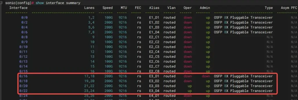
- Local: CX864E-N, initially configured with
ethernet 0/16as 4x200G breakout, link UP. - Remote: CX732Q-N, with two 400G DR4 modules both configured as 2x200G breakout.
Symptoms:
When performing a 4x200G breakout on an 800G DR8 module, shutting down one sub-interface triggers a link-down event on the others. Specifically, issuing a shutdown command on interface 0/16 causes interfaces 0/18, 0/20, and 0/22 to also go down.
Root Cause:
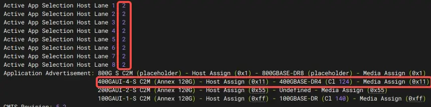
Without CMIS enabled, the 800G-DR8 module defaulted to Application Code 2 (400GBASE-DR4 mode). This mismatch between the module’s configured speed and the interface’s actual data rate caused the sub-interfaces to interfere with each other.
Resolution:
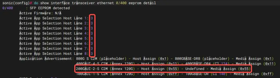
Once CMIS was enabled, the system automatically identified the port requirements and selected Application Code 3 (200GBASE-DR2 mode). With the electrical interface speed now correctly matched, the link immediately stabilized.
Following this change, shutting down ethernet 0/16 no longer impacts interfaces 0/18, 0/20, and 0/22. Because the module is now locked to the correct 200GBASE-DR2 mode, the four sub-interfaces operate independently at the module’s datapath level, preventing cross-interface status instability.
Case 2: 800G DR Module Fails to Link Up in 100G Breakout
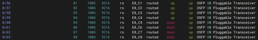
Symptoms:
Upon inserting the module, the status LED remains off, and all associated interfaces stay down.
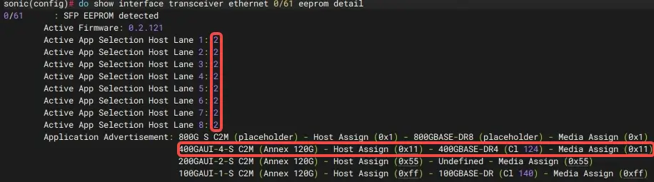
Root Cause:
The module defaulted to an incorrect “400G mode” and failed to recognize the required 100G lane configuration.
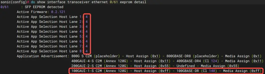
Resolution:
With CMIS enabled, the protocol automatically aligned the rate mode to “4” (100G mode) based on the port configuration. Once the parameters were synchronized, the link came up immediately.
By integrating CMIS, AsterNOS running on our data center switches ensures physical layer stability while providing a visual management interface through the operations platform.
Get Expert Consultation for Your Data Center
While CMIS enables automated and intelligent management of high-speed links, building a robust 800G/1.6T AIDC network requires precise architectural design and deep technical experience.
If you are planning a high-performance AI compute cluster or facing technical bottlenecks with multi-vendor, multi-rate optical module interoperability, we are here to help:
- Access Technical Guides: If you are building a high-performance GPU backend network, check our configuration guide on GPU Backend Fabric Design Guide for AI Compute Network for comprehensive deployment strategies.
- Book an Expert Consultation: Schedule a free network architecture assessment with our senior engineering team. We provide one-on-one diagnostics to identify hidden risks and offer actionable optimization recommendations.
FAQ
Is CMIS backward compatible?
Yes, CMIS is designed with modularity in mind. While it represents a major shift from legacy SFF standards, it provides standardized register mappings that allow modern high-speed transceivers to communicate efficiently with compatible switch ports.
Does my existing switch support CMIS?
It depends on your hardware and NOS (Network Operating System). Asterfusion switches running our enterprise SONiC-based NOS support CMIS protocols, enabling you to leverage advanced telemetry for your backend network.
How does CMIS impact GPU cluster uptime?
By providing granular signal quality metrics (like pre-FEC BER), CMIS allows your network management platform to detect “slow-failing” transceivers before they trigger a full link-down event, effectively preventing unplanned downtime in AI workloads.


