Table of Contents
Introduction
Selecting the right optical transceivers for NVIDIA ConnectX NICs can be a minefield of proprietary white-lists and complex physical specs. To simplify your deployment, in this article, we provide a detailed selection matrix for ConnectX-5 through ConnectX-8 transceivers, followed by proven field strategies to bypass vendor lock-in. Our goal is to ensure your network remains both high-performing and cost-effective.
Learn About Optical Transceiver Types
Let’s review the fundamentals of optical transceivers with The Most Comprehensive Guide of Optical Modules.
Based on transmission distance, optical transceivers are typically classified into the following categories:
Suffix | Full Name | Medium | Typical Reach | Key Characteristics and Use Cases |
SR | Short Reach | Multimode Fiber | <100 m | Lowest-cost option for short-distance links within data centers, such as intra-rack and inter-rack connectivity. |
DR | Data Center Reach | Single-Mode Fiber | 500 m | Designed for Spine-Leaf fabrics in data centers. Widely adopted for silicon photonics deployments. |
FR | Fiber Reach | Single-Mode Fiber | 2 km | Suitable for medium-distance links across data halls, buildings, or campus environments. |
LR | Long Reach | Single-Mode Fiber | 10 km | Commonly used for campus interconnects and metro access networks, with ample link budget. |
ZR | Extended Reach | Single-Mode Fiber | 80 km+ | Uses coherent optics for metro and long-haul intercity transmission. |
Learn About Cable Types
Read AOC, DAC, ACC, and AEC Cables: The Most Complete Overviewto understand the differences between the major direct-attach and active cable types.
How to Select Optical Transceivers for NVIDIA ConnectX NICs
When building an AIDC cluster, efficient connectivity between switches and compute nodes starts with selecting the right optical transceivers for the NVIDIA ConnectX NICs. Each ConnectX generation differs in link speed, PCIe interface, and form factor. Choosing an incompatible transceiver can limit available bandwidth or even prevent the link from coming up.
The following compatibility matrix provides the recommended optical transceiver options for the NVIDIA ConnectX-5 through ConnectX-8 product families.
NIC Model | Maximum Link Speed | PCIe Interface | Common Form Factor | Recommended Interconnect |
100GbE / EDR 100G InfiniBand | PCIe Gen3 / Gen4 | SFP28 / QSFP28 | In-rack: 100G DAC or AOC Inter-rack: 100G SR4 or CWDM4 | |
200GbE / HDR 200G InfiniBand | PCIe Gen4 | QSFP56 | In-rack: 200G DAC or AOC Inter-rack: 200G SR4 or FR4 | |
400GbE / NDR 400G InfiniBand | PCIe Gen5 | OSFP / QSFP112 | In-rack: 400G DAC or AOC Inter-rack: 400G DR4 (MPO-12/APC) | |
800GbE / X800 InfiniBand | PCIe Gen6 | OSFP | In-rack: LPO or AEC Inter-rack: 800G 2×SR4 or 2×DR4 |
1. Start with the NIC model: Select the interconnect based on the NIC generation first. For example, ConnectX-7 is available with both OSFP and QSFP112 ports, while ConnectX-8 primarily adopts OSFP. Ensure the switch-side transceiver uses the same form factor as the NIC port to avoid physical incompatibility.
2. Match the link speed: The maximum NIC link speed determines the required switch port speed, but it is only one part of the selection process.
3. Choose the transmission medium based on distance:
- In-rack links (<3 m): DAC is the preferred option, offering the lowest cost and minimal latency. For 800G deployments, LPO or AEC can further reduce power consumption and thermal output compared to traditional pluggable optical transceivers.
- Inter-rack or data hall links: Select the appropriate optical transceiver based on the transmission distance. For 400G and higher-speed AI networks, pay close attention to the fiber connector type. Parallel single-mode optical modules require APC connectors (green, 8° angled polish). Using UPC connectors (blue, flat polish) can introduce excessive insertion loss and may even damage the optical interface.
Following this compatibility matrix helps minimize link failures caused by incompatible interconnects and ensures the GPU cluster operates at its full network performance.
Physical and Logical Considerations for Switch-to-Server Connectivity
The compatibility matrix above provides a good starting point for selecting optical interconnects. In practice, you should also consider the following hardware and software requirements.
- Hardware Considerations: Thermal Design and Connector Requirements
- OSFP thermal design (Flat-top vs. Heatsink):ConnectX-7 and ConnectX-8 primarily adopt the OSFP form factor because it provides better thermal performance than QSFP. Its larger size allows for improved heat dissipation and supports integrated heatsinks. When selecting OSFP modules, match the thermal design to the target device. Switches typically require Flat-top modules, while NICs often require Heatsink modules to meet airflow and cooling requirements. These two variants have different mechanical designs and are not interchangeable. Always verify the NIC vendor’s thermal requirements before deployment.
- APC connector requirements: The two common fiber connector end-face types are UPC (blue, flat polish) and APC (green, 8° angled polish). High-speed parallel single-mode optical modules, such as DR4, require APC connectors. Never use UPC patch cords with these modules. Connector mismatch can introduce excessive insertion loss and may physically damage the optical interface.
Once the NIC model and switch port specifications are identified, optical transceiver selection becomes a straightforward process. Mechanical compatibility, thermal design, and connector types all follow well-defined industry standards.
- Software Configuration: FEC Alignment in PAM4 Networks
PAM4 links (50G to 200G per lane) are highly sensitive to signal quality. Both ends of the link must use the same Forward Error Correction (FEC) mode. A mismatch can prevent the link from coming up.
- Special consideration for 100G DR1: The 100G DR1 module converts four 25G NRZ electrical lanes, commonly used by legacy 100G NICs and switches, into a single 100G PAM4 optical signal. Because the electrical and optical interfaces use different signaling schemes, FEC conversion is handled internally by the module’s DSP.
- Deployment recommendation: When using 100G DR1 modules, manually disable FEC on the switch port. Enabling NRZ FEC on the switch can conflict with the module’s internal DSP processing, preventing the link from coming up.
Optical Transceiver Compatibility and “Whitelist” Locking Mechanisms
Optical transceiver compatibility and whitelist-based locking are mechanisms used by some major switch vendors to enforce ecosystem control. These mechanisms ensure that only certified optical modules are allowed to operate on the platform.
At the hardware and firmware level, different validation layers are typically implemented:
- Level 1 – Basic validation: The switch reads EEPROM fields such as Vendor Name, OUI, and Part Number. If the module is not in the whitelist, the port is placed into an err-disable state.
- Level 2 – Checksum validation: The system verifies CC_BASE and CC_EXT checksum fields. This prevents simple EEPROM modifications used to spoof vendor identity.
- Level 3 – Proprietary cryptographic handshake: A more strict mechanism based on proprietary hash or public/private key authentication stored in reserved EEPROM regions. If signature verification fails, the link is rejected.
- Level 4 – Full policy enforcement: Advanced enforcement policies may disable power delivery, mark the module as Unsupported, or restrict access to telemetry and diagnostic functions.
How to Handle Optical Transceiver Compatibility Issues
Compatibility issues typically fall into three categories. Each requires a different troubleshooting approach.
Scenario 1: Vendor Lock-in
This usually occurs on platforms from major vendors such as NVIDIA, Cisco, or Huawei.
- Symptom: After EEPROM validation, mismatched Vendor Name, OUI, or cryptographic signature triggers err-disable or power denial.
- Resolution approach:
- Method A – EEPROM reprogramming / emulation: The most commonly used field practice. The module EEPROM is reprogrammed to match a vendor-approved identity. This effectively emulates a “whitelisted” module and bypasses software validation checks.
- Method B – Approved optics list: Use vendor-certified optics or third-party modules that have passed formal interoperability testing with the platform.
Scenario 2: Protocol or Specification Mismatch
This is a pure compatibility issue unrelated to locking mechanisms, but it is a common cause of link failures.
- Symptom: Physical link is present and optical power levels are normal, but the link cannot be established.
- Common causes:
- FEC mismatch: One side uses RS-FEC while the other uses FC-FEC or no FEC, resulting in link negotiation failure.
- Speed or lane mismatch: For example, attempting to interconnect 100G DR1 (PAM4) with legacy 100G NRZ interfaces without DSP-based adaptation.
- Electrical parameter deviation: Some NICs enforce strict voltage or signal conditioning requirements, which generic optics may not satisfy.
- Resolution approach: Align port configuration (FEC mode, speed, and signaling type). If misalignment persists, replace the module with one that matches the required interface specification.
Scenario 3: Firmware or Driver Incompatibility
This is commonly observed on NIC-side deployments, especially when the optical module is not included in the vendor’s compatibility database.
- Symptom: The OS can detect the module and even read optical diagnostics, but the link fails to come up.
- Resolution approach:
- Firmware or driver upgrade: Older NIC firmware may not recognize newer optical modules. Updating firmware or drivers often resolves the issue.
- Identity emulation (“re-badging”): In environments without encrypted enforcement, the module may be reprogrammed to emulate a vendor-approved part number, allowing the driver to load the correct optics profile.
Optical Transceiver Selection Case Studies
In large-scale data centers and AI computing clusters, optical transceiver selection is primarily driven by two key dimensions: link speed and transmission distance. These are further constrained by requirements for low latency and low loss in specific deployment scenarios.
Case 1: Hyperscale Cloud Data Center (400G Backbone Network)
In a traditional Spine-Leaf architecture, the primary objective is to balance cost efficiency with flexibility for intra–data center connectivity.
Server Layer → Leaf (Intra-rack / Adjacent-rack connectivity):
- Use case: Connectivity for ConnectX-5-class 100G NICs, typically within 3 meters.
- Selection logic: At this distance, 100G DAC is the most cost-effective choice. For higher cabling density or improved cable management, 100G AOC can be used to reduce cable weight and provide a better bend radius.
Leaf → Spine (Inter-row / Inter-data center connectivity):
- Use case: Links across ToR switches or between data halls, typically ranging from 50 m to 500 m.
- Selection logic: At this distance, DAC is no longer applicable. Optical transceivers are required. Recommended options include 400G DR4 (up to 500 m) and 400G FR4 (up to 2 km) . The physical medium is OS2 single-mode fiber, typically deployed with high-density MPO or LC patch cords, ensuring signal integrity for long-distance transmission.
Case 2: Large-Scale AI Compute Cluster (800G IB / RoCEv2 Network)
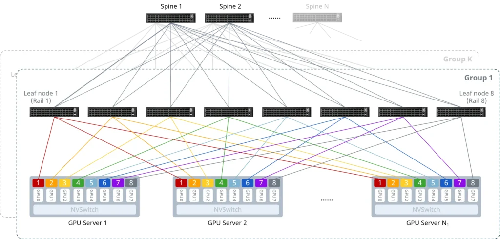
800G AI clusters are extremely sensitive to both bandwidth throughput and latency. High-density interconnects in compute nodes such as H100 / H800-class systems impose stringent requirements on link stability and performance.
Compute Node → Leaf (Server-side connectivity):
- Use case: DGX H100-class systems, typically equipped with up to 8× 800G NICs per node, requiring extremely high aggregate bandwidth.
- Selection logic: Since interconnect distances are relatively short (in-rack or adjacent-rack), the preferred options are 800G AOC or 800G SR8 multimode optics. These solutions use OM4/OM5 multimode fiber, enabling low-latency transmission while optimizing overall cost efficiency.
Leaf → Spine (Cluster backbone interconnect):
- Use case: High-throughput backbone links responsible for bulk data movement across the AI cluster.
- Selection logic: The recommended option is 800G 2×DR4 single-mode parallel optics. This architecture enables flexible breakout designs and improves infrastructure reuse across different layers of the network.
Key Design Considerations:
- Interface compatibility: Always verify switch port form factors, such as OSFP vs QSFP112, to ensure physical compatibility. Mismatched form factors can lead to direct interoperability failure.
- Insertion loss control: AI networks operate with strict tolerance for packet loss. In single-mode deployments, APC (angled polish) connectors must be used. This reduces back-reflection and minimizes signal jitter and bit errors, ensuring stable link performance at 800G speeds and maintaining overall link robustness.
Troubleshooting SOP for Optical Transceivers and Link Failures
For more operational guidance on diagnosing optical Transceivers and link issues, refer to the following SOP:
A Detailed Checklist for Link Failures Troubleshooting in AI Data Centers


