Table of Contents
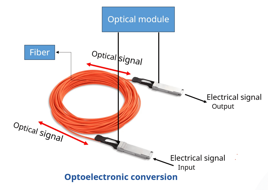
What is an optical module?
The optical module serves as a crucial component in optical fiber communication systems, operating at the physical layer, which is the lowest layer in the OSI model. Its primary function is to achieve optoelectronic conversion by converting electrical signals into optical signals and vice versa.
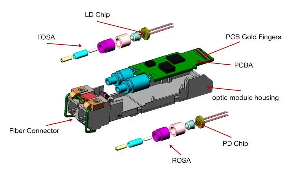
Optical Module Components
An optical module usually consists of an optical transmitting device (TOSA, including a laser), an optical receiving device (ROSA, including a photodetector), functional circuits,main control circuit board (PCBA), housing and optical (electrical) interface and other components.
How do optical modules work?
What is TOSA?How does it work?
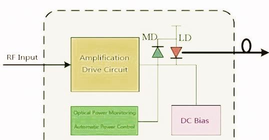
The Transmitter Optical Sub Assembly (TOSA) is responsible for the emission of light. Its primary function entails converting electrical signals into optical signals. This assembly comprises a light source, such as a laser diode or a semiconductor light-emitting diode (LED), an optical interface, a monitoring photodiode, a housing made of either metal or plastic, and an electrical interface.
Presently, laser diodes (LD) are commonly used as the light source in most optical modules. These diodes exhibit advantages such as lower power consumption, higher output power, and improved coupling efficiency compared to semiconductor light-emitting diodes (LED). However, LED remains a viable option for low-rate and short-distance transmissions due to its lower cost and longer lifespan.
After the input electrical signal is processed by the internal driver chip, it drives the laser diodes (LD) or light-emitting diodes (LED) to emit a modulated optical signal at a corresponding rate. Additionally, an automatic optical power control circuit (APC) is integrated into the TOSA, ensuring a consistently steady output optical signal power
What is ROSA?How does it work?
The ROSA, or Receiving Optical Sub-Assembly, is an essential component in optical communications. Its primary role is to convert the optical signal transmitted from the TOSA into an electrical signal. The ROSA consists of various elements, including a photodetector (either a PIN photodiode or an avalanche photodiode), Trans-impedance Amplifier (TIA) , and a Post Amplifier.
Photodetectors play a crucial role in optical communications, with PIN photodiodes and APDs being the most common types. APDs are particularly sensitive photodetectors that utilize the avalanche multiplication effect to amplify the photocurrent, resulting in a receiver sensitivity improvement of 6 to 10 dB compared to PIN photodiodes.
The weak signal current generated by the photodetector undergoes conversion into a signal voltage of adequate amplitude through Trans-impedance Amplifier (TIA). This voltage signal is initially analog and must be transformed into a digital signal before being recognized by the signal processing circuitry. The Post Amplifier, positioned after the TIA, plays a vital role in converting signals with varying amplitudes into digital signals of equal amplitude.

The ROSA and TOSA components, when paired together, form the fundamental elements of an optical module utilized for transmitting and receiving signals.
What is PCBA?
PCBA refers to integrated circuit board, also known as printed circuit board. SMT patches and DIP plug-ins are commonly used methods in the PCBA production process.The whole process of PCB blanking through SMT mounting or DIP plug in is called PCBA.Active and passive electronic components are soldered to an integrated circuit board and then placed inside an optical module. Simply put, PCBAs are thin boards that hold integrated circuits and other electronic components to ensure the quality, functionality, etc. of electronic devices.
What is Fiber optic connector?
Fiber optic connector here refers to the interface where the optical module connects to a fibre optic patch cable, which can be connected via a single-mode or multi-mode fibre optic cable.
What is Digital Diagnostic Monitoring(DDM)?
Digital Diagnostic Monitoring is a technology that enables real-time monitoring of various parameters in optical modules. These parameters include operating voltage, operating temperature, received optical power, transmitted optical power, and laser bias current. This cutting-edge technology, developed by the industry organization SFF Committee, adheres to the standard parameters outlined in the SFF-8472 Multi-Source Protocol. These standards ensure that the hardware and software of optical modules and network equipment follow a consistent set of values and ranges. Ultimately, this promotes the interoperability of products offered by both network equipment vendors and optical module vendors.
Key performance metrics for optical modules
How to measure the performance index of optical modules? To better illustrate these complex concepts, let’s compare the function of an optical module to that of a courier. Its task is quite similar to that of a courier in real life. At the transmitting end, it “picks up” the information (electro-optical conversion) and transports it to the designated destination. Similarly, at the receiving end, it “delivers” the information (optical-electro conversion to the destination。
Transmitter end :
Average output power
Average output power refers to the optical power output by the light source under normal working conditions and can be understood as the intensity of light. The transmitted optical power is influenced by the proportion of “1” in the data signal. The more “1”s present, the greater the optical power. When sending a pseudo-random sequence signal, the proportions of “1” and “0” are approximately equal. The power measured at this time represents the average transmitted optical power and is usually expressed in W or mW or dBm. In communications, dBm is commonly used to represent optical power, with the unit conversion formula: P(dBm) = 10Log(P/1mW).

The average output power plays a crucial role in determining the signal transmission distance. It acts as the “physical strength” of the courier, similar to how a courier needs sufficient physical strength to deliver a package to a distant location. Insufficient power might cause the signal to “fail” halfway.
Extinction ratio
The extinction ratio is the minimum value of the average optical power ratio of a laser under full modulation conditions when transmitting all ‘1’ codes to the average optical power of the laser when transmitting all ‘0’ codes. It is expressed in dB. The extinction ratio serves as a measure of the operating efficiency of the laser.
It can be considered as the “concentration” of a courier accurately distinguishing different packages to ensure error-free and swift delivery. A higher extinction ratio, indicating a greater distinction between “1” and “0”, results in clearer signals and higher quality of transmission. Typical minimum values of the extinction ratio range from 8.2dB to 10dB.
Center wavelength
The optical module’s center wavelength refers to the wavelength it uses while operating. It achieves the best transmission effect when the optical module matches the center wavelength of the optical signal it transmits. Various lasers, including those of the same kind, may have different center wavelengths due to factors such as manufacturing and production processes. Even the same laser might have different center wavelengths under different conditions. To address this, manufacturers of optical devices and modules provide users with a parameter called the center wavelength which generally represents a range. Currently, the three main center wavelengths for commonly used optical modules are the 850nm band, 1310nm band, and 1550nm band.
To illustrate, we can use an analogy. Imagine a courier needing to transport a package during rush hour. The courier cannot freely choose any route as they might encounter traffic jams. Instead, they require a well-planned route that allows them to avoid congestion, take the fastest path, and ensure on-time delivery of the package. Fiber optics can be likened to a city road network, with the center wavelengths representing the chosen routes of the courier. If the courier selects a congested road (incorrect wavelength), the package may be delayed regardless of their speed. Conversely, if they choose a clear road (the correct wavelength), they can reach their destination more quickly.
Receiving end:
Receiving Sensitivity
Receiving sensitivity, on the other hand, signifies the minimum average input optical power that the component at the receiving end of the optical module can detect under certain BER (BER=10(-12)) conditions. If Average Output Power represents the light intensity at the transmitting end, receive sensitivity denotes the light intensity that the optical module can detect. The unit of measurement for receive sensitivity is dBm. This is akin to a courier’s level of attentiveness, determining the optical module’s ability to detect weak light signals. If the module’s perception of weak signals is inadequate, some weak signals may be overlooked, similar to how a careless courier might lose small parcels. Generally, higher data rates correspond to poorer reception sensitivity, indicating higher requirements for the optical module’s receiving end devices. Just like during Black Friday, where the volume of express deliveries surges, only exceptional couriers can ensure that none of the parcels are lost.
Receive power
Receive power refers to the average optical power that the components at the receiving end of the optical module can accept while maintaining a certain Bit Error Rate (BER=10(-12)). It is measured in dBm. The upper limit of receive power is the overload optical power, while the lower limit is the maximum value of received sensitivity.
Broadly speaking, if the received optical power is less than the reception sensitivity, it may not be able to receive signals normally because the optical power is too weak. If the received optical power is greater than the overload optical power, it may not be able to receive the signal normally because of the error code phenomenon.
Analogous to the responsibility of a courier, the received power represents the level of responsibility. A higher received power indicates a more responsible courier who avoids missing any small parcels or committing errors. In a day’s work, a courier has to deliver a large number of parcels. Some parcels have clear bar code printing, while others may have blurred bar codes due to various reasons. If the courier lacks a strong sense of responsibility, mistakes can occur when handling blurred barcode parcels, resulting in incorrect deliveries or delayed delivery. In extreme cases, even the smallest parcel requests from customers may go unattended.
Overload optical power
Overloading of optical power, also known as saturated optical power, refers to the maximum allowable optical power that the optical module can withstand without causing signal “explosion” and subsequent data loss. The unit of measurement for overload optical power is dBm. This can be likened to the maximum capacity of a courier to deliver goods. It is important to note that when the photodetector is exposed to intense light, it may experience photocurrent saturation. During this phenomenon, the detector requires a certain amount of time to recover. Consequently, the receiving sensitivity decreases, potentially resulting in misjudged signals and code errors. Exceeding the overload of optical power can lead to equipment damage. Thus, it is essential to avoid exposure to strong light to prevent exceeding the overload of optical power.

By considering these key indicators, our exceptional courier, the optical module, ensures efficient and accurate data transmission. In the upcoming sections, we will delve into the classification of optical modules, future trends, and guidelines for selecting the appropriate optical module for your network.
Classification of Optical Modules
The editor has compiled a list of optical module classifications for the reader. In the following, the classification of optical modules according to this table is described in detail.
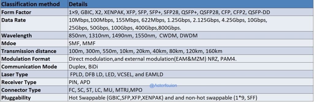
Classification by package type

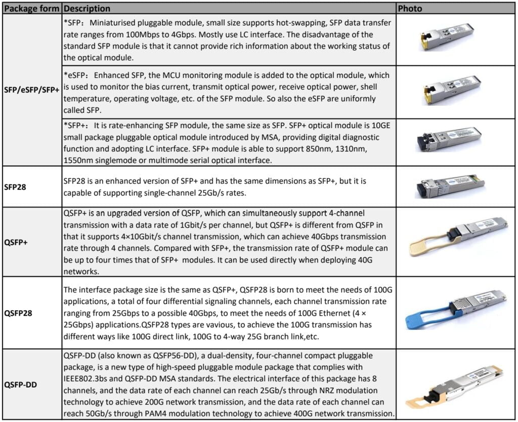
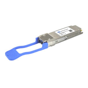
The optical module form factors pertain to the physical dimensions of the module, determining its size and shape, which is vital for compatibility with other network devices. With the rapid advancement of optical modules, their size is continuously shrinking, leading to the introduction of new standards every few years. The Asterfusion switches utilize the following packaging options: QSFP-DD, QSFP28, QSFP+, SFP28, SFP/eSFP, SFP+, CXP, CFP, and so on.
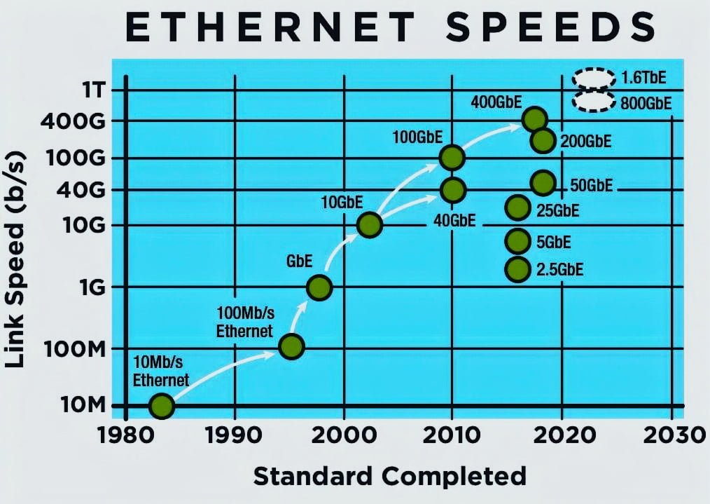
Classification by rate
In order to meet the needs of various transmission rates, there are different rates of optical modules: GE optical modules, 10GE optical modules, 25GE optical modules, 40GE optical modules, 100GE optical modules, 400GE optical modules, 800GE optical modules
Classification by laser type
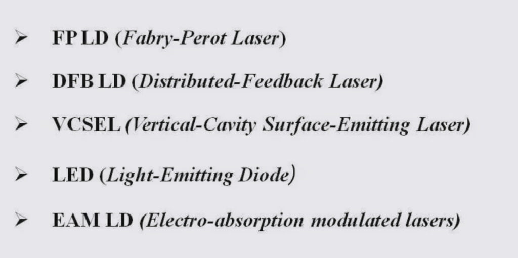
The selection and utilization of optical modules vary greatly depending on different scenarios. One crucial aspect to consider is the laser type chosen based on the transmission distance. The laser plays a vital role in the optical module, representing nearly 50% of its cost. There are several laser types available, including FPLD, DFB LD, LED, VCSEL, and EAMLD. In the future, we will delve into a detailed explanation of each laser type, offering a comprehensive understanding of their functionalities.
Classification by centre wavelength
Above we have explained the concept of what is centre wavelength. At present, the commonly used wavelengths are 850nm, 1310nm and 1550nm, as well as CWDM wavelengths of 1270-1610nm and DWDM wavelengths of 1525-1565nm or 1570-1610nm. 850nm wavelengths are usually used with multimode optical fibers, which are mostly used for short-distance transmission, while 1310nm wavelengths are usually used with single-mode fibers, which are mostly used for medium- and long-distance transmission.
Expanded Knowledge: What are CWDM and DWDM modules?
What is CWDM?
In an optical communication system, different optical signals can be transmitted simultaneously in the same optical fibre by Wavelength Division Multiplexing (WDM) technology.
The CWDM optical module adopts Coarse Wavelength Division Multiplexing (CWDM ) technology, which can combine optical signals of different wavelengths through an external wavelength division multiplexer. One optical fiber can be used as multiple optical fibers, which can simultaneously realize multi-service transmission services that are completely independent of each other. The technology of ensuring independent bandwidth can also save optical fiber resources. At the same time, the receiving end needs to use a wave decomposition multiplexer to decompose the complex optical signal.
What is DWDM ?
DWDM belongs to the Dense Wavelength Division Multiplexing (DWDM) technology, which can couple different wavelengths of light into a single-core optical fibre for one transmission.The channel spacing of the DWDM SFP has different intervals of 0.4 nm, 0.8 nm, 1.6 nm and so on according to the need, and smaller intervals require additional wavelength control devices.A key advantage of DWDM SFP is that it is protocols and transmission speeds that are not correlated.
Classification by mode:
- The central wavelength of single mode optical module is generally 1310nm, 1550nm, which is used with single mode optical fibre. Single-mode optical fibre transmission bandwidth, transmission capacity, suitable for long-distance transmission.
- The central wavelength of multi-mode optical module is generally 850nm, and multi-mode optical fibre supports the use. Multi-mode optical fibre has mode dispersion defects. Its transmission performance is worse than single-mode optical fibre, but the cost is low, suitable for smaller capacity, short distance transmission.
Expanded Knowledge: What are Optical fibres ?
Optical fibres are hair-thin bundles of glass or plastic filaments that can transmit optical signals over long distances in the same way that cables transmit electricity. Optical fibre is widely used in telecommunication, data communication and other fields.
Typically, a transmitter at one end of an optical fibre uses a light emitting diode (LED) or a laser beam to transmit light pulses into the fibre, and a receiver at the other end of the fibre uses a photosensitive element to detect the pulses.
Optical fibers are divided into single-mode optical fibers and multi-mode optical fibers. In order to use different types of optical fibers, single-mode optical modules and multi-mode optical modules are produced.
Single-mode fibre
- Single-mode fibres have a core diameter of 9μm and a cladding diameter of 125μm.
- Low loss, long transmission distance
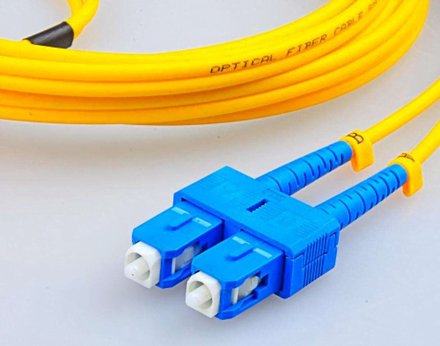
- Colour: Generally, single-mode fibre patch cord is yellow, connector and protective sleeve are blue.
Multi-mode fibre
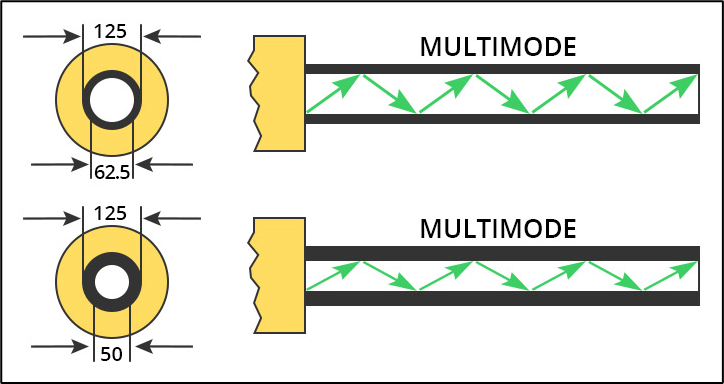
- Multi-mode fibre has a core diameter of 50~62.5μm and a cladding outer diameter of 125μm.
- Large mode dispersion, short transmission distance, low cost
- Colour: generally, multi-mode fibre patch cord OM1 and OM2 are orange, OM3 is lake blue, and OM4 is purple. connector and protective sleeve are expressed in beige or black.
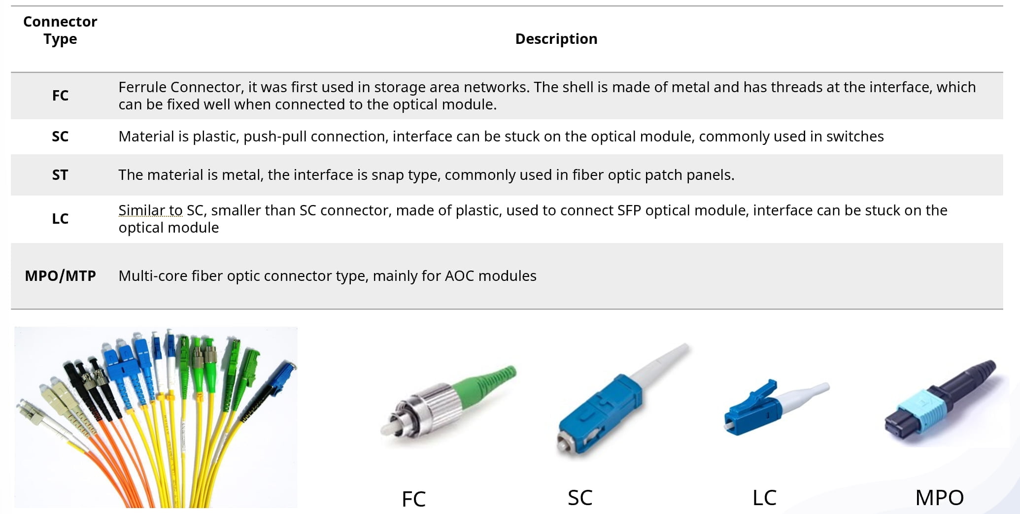
Classification by connector type:
Connection of optical modules commonly used jumper connector, these are FC interfaces, SC interfaces, ST interfaces, LC interfaces, MPO interfaces, etc.
Classification by modulation formats
Optical module modulation involves key processes such as the generation, transmission, and reception of optical signals. The purpose of optical module modulation technology is to achieve high-speed, efficient and reliable communication by changing the intensity, phase or encoding method of variable light signals.
Direct and external modulation(EAM&MZM)
Modulators can be divided into laser direct modulation and laser external modulation. The direct laser modulation method is simple and economical, but has large chirp, wide spectrum, and limited dispersion. It is generally used in short-distance scenarios with rates below 25Gbit/s.
external modulation requires the use of an additional modulator outside the laser, which is complex and costly to implement, but can achieve higher rates and longer transmission distances. Depending on the type of modulator, external laser modulation is divided into Electro Absorption Modulator (EAM) and Mach-Zehnder Modulator (MZM), which are used in long-haul scenarios at 10Gbit/s and 40Gbit/s, and in ultra-long-haul scenarios at 40Gbit/s and 100Gbit/s and above, respectively.
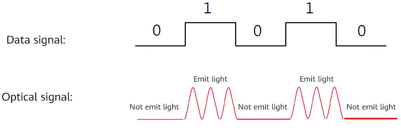
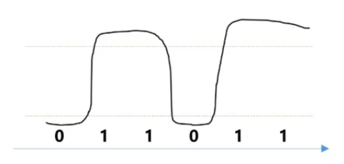
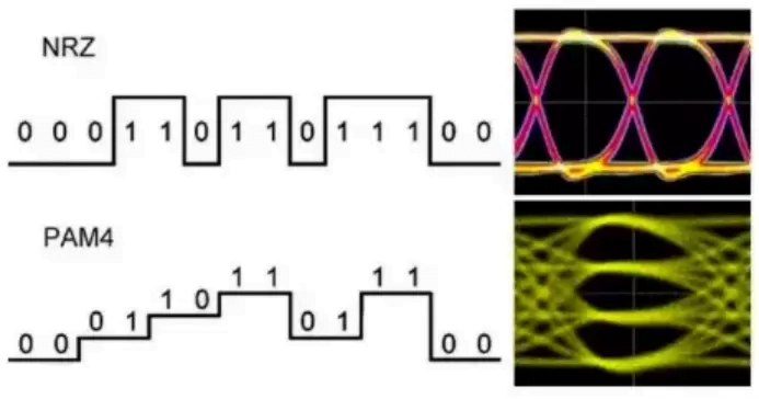
NRZ Modulation
Ethernet technology has largely used NRZ since its introduction in the 1980s. With NRZ modulation, the high/low optical power from a laser corresponds to binary 1 and 0 signals, respectively, and 1bit of information can be transmitted per clock cycle. The disadvantage is that there may be limitations for high-speed data transmission. The following diagram shows
PAM4 modulation
After developing to 100GE, Ethernet technology encountered a bottleneck in bandwidth improvement, mainly because the physical layer technology faced challenges driven by low cost. When discussing the IEEE802.3bs standard solution for 400GE, some manufacturers proposed using Pulse Amplitude Modulation 4 (PAM4) technology to replace NRZ for the physical layer modulation code type.
PAM4 modulation divides the power of the optical signal into four different thresholds, corresponding to the binary signal states 00, 01, 10 and 11 respectively.
Each clock cycle can transmit 2 bits of information, so the baud rate is twice that of NRZ. That is, the transmission efficiency is doubled.
Classification by transmission distance
The transmission distance is the courier’s “service range”. This indicator tells us how far the optical module can send the signal. If the service range is too small, some further destinations will not be able to be sent.
Optical module transmission distance can be divided into short distance, medium distance and long distance three, generally regarded as 2km and below the transmission distance for the short distance, between 10 ~ 20km transmission distance for the medium distance, more than 30km transmission distance for the long distance.
Optical signals in the transmission process will produce dispersion and loss. Dispersion and loss are the main factors affecting the transmission distance of the optical module.
- Dispersion: Generally, single-mode transmission does not produce inter-module dispersion, while multi-mode transmission supports multiple transmission modes, light will be refracted many times, which will produce inter-module dispersion, the larger the dispersion, the shorter the transmission distance of the optical module.
- Loss: Different wavelengths of optical transmission loss is different, from large to small in order of 850nm>1310nm>1550nm, the smaller the loss, the longer the transmission distance of the optical module.
Classification by mode of operation of optical interfaces
Duplex fiber
Duplex fiber: This type of fiber optic cable comprises two separate fiber strands, allowing for simultaneous two-way communication. One fiber strand is dedicated to transmitting data, while the other is used for receiving data.
BiDi fiber
BiDi fiber optic cables, also known as bidirectional fiber, utilize a single fiber for both transmitting and receiving signals. By employing WDM (Wavelength Division Multiplexing) technology, different center wavelengths are utilized in the transmitting and receiving directions. Generally, optical modules have two ports, one for transmitting (TX) and the other for receiving (RX). On the other hand, BiDi modules have only one port capable of transmitting 1310nm optical signals and receiving 1550nm optical signals simultaneously, or vice versa. Thus, these modules need to be used in pairs. The major advantage of BIDI modules is their ability to conserve fiber resources.
Classification by pluggability
Hot-swappable means that optical modules can be inserted or removed from a running system without interrupting system operation. This feature makes it easy to install, maintain and upgrade optical modules without powering down the device.Asterfusion’s optical modules are all hot-swappable.
We have finished summarising the types of optical modules, I believe that you currently have a general understanding of the knowledge of optical modules.
Factors need to consider for choosing the right optical module
When selecting the right optical module, consider factors like transmission speed, usage environment, connector type, fiber type, transmission distance, optical wavelengths, fiber transceiver type, As well as two more factors to consider :opt for optical modules that adhere to MSA (multi-source agreement) and IEEE specifications to ensure compatibility and industry standardization. Select vendors that offer robust after-sales service and technical support to address any potential issues after the purchase.
Optical modules’ extensive applications
- Broadband Access: Optical modules are used in broadband access to establish high-speed Internet connections between users and service providers.
- Enterprise networks: Optical modules are essential for connecting servers, switches, and routers in enterprise networks, ranging from small offices to large campuses, to achieve fast LAN connections.
- Data center network: Data centers rely on optical modules to establish seamless data connectivity between servers, switches, and storage devices, resulting in efficient data exchange within the data center environment.
- In mobile communication base stations, optical modules facilitate interconnections among different devices. 1.25G, 2.5G, 6G, and 10G optical modules are predominantly utilized for connecting BBU and RRU equipment in 4G networks.
- Metropolitan area networks, backbone networks, and wide area networks make use of passive wavelength division systems. CWDM and DWDM optical modules are commonly employed to combine and transmit optical signals in these scenarios.
- SAN (Storage Area Network) and NAS (Network Attached Storage) networks rely on optical modules to ensure smooth data storage. The SAN storage network employs optical modules that support the FC Fiber Channel protocol, while the NAS storage network utilizes optical modules complying with the Ethernet protocol.
- Optical modules serve as a crucial component of the 5G bearer network, enabling interconnection among devices at each layer. 25G SFP28 optical modules are utilized in the 5G fronthaul network, and the mid-backhaul network employs 25G, 50G, 100G, 200G, and 400G optical modules.
Emerging data transmission standards–800G and 1.6T
Generative AI, represented by ChatGPT, is at the forefront of a new technological revolution. Currently, major cloud vendors have deployed 200G and 400G optical modules in data centers, and with the clear development trend of AIGC, the demand for even higher-speed 800G and 1.6T optical modules is catalyzed by the need for high computing power. Although 400G optical modules have not yet dominated the market on a large scale, the inconspicuous rise of 800G optical modules has begun. Several vendors have already released their 800G optical module products, but the industry is not yet mature, and we may see large-scale deployment by 2025. Furthermore, AI’s major clients have expressed a clear demand for 1.6T optical modules to match the future requirements of GPUs with higher bandwidth and computing power. The progress of 1.6T in 2024 will primarily focus on testing, certification, and meeting small-volume demand. The real scaling up is expected to commence in 2025-2026.
To expand your understanding of optical modules, we will continue to publish insightful articles on this topic. Asterfusion is committed to delivering valuable and practical content on optical modules in the future.
At Asterfusion, we specialize in producing and selling enterprise SONiC-based open network switches and optical modules, as well as active optical cables, direct-connect copper cables, and other optical components. Our goal is to become a renowned supplier of open network switches and optical network components. We offer innovative designs, reliable quality, and cost-optimized solutions to meet the high-speed interconnect needs of global enterprise networks, data centers, cloud computing, 5G and metro telecommunications, and ultra-high-definition video services.
Reference
- Mathieu, C& Michael J.Y(2015) “Optical Cables for Consumer Applications “Journal of Lightwave Technology
- Marco, M& Scott, S (2008) “SFP+ Interoperability Demonstration White Paper Version 1.0 “
- White Paper “Understanding DWDM & Optical Communication Giacomo Losio”, September 2014
- Mathieu, C & Michael J.Y(2015) Optical Cables for Consumer Application Journal of Lightwave Technology
- Jianyu, L (2019) ” Design of High-Speed Optical Receiver Module for 160Gb/s NRZ and 200Gb/s PAM4 Transmissions ,2019 IEEE International Symposium on Circuits and Systems (ISCAS)
- China Optical Networking Symposium ‘5G Bearer Optical Module White Paper’ 26 Aug 2020
- “Optical Module Industry In-Depth Report,’ Debonair Securities Industry In-Depth Report 14 Jul 2019
- Optical module – Wikipedia
Related products


800G Optical Modules: Everything You Need to Know in This Article
Fiber Optic Connectors:How to Choose From LC/FC/SC/ST/MU/MPO/MTP?
Buying Guide of Ethernet cable: Cat5, Cat5e, Cat6, Cat6a, Cat7, and Cat8
The Most Complete Overview of Multimode Fibres -OM1, OM2, OM3, OM4 & OM5


