Asterfusion is revolutionizing campus networking with its cutting-edge end-to-end BGP EVPN solution and OpenWiFi-compatible systems. Built on a robust Clos architecture, Asterfusion’s BGP/VxLAN EVPN underlay network ensures unmatched flexibility, seamlessly forwarding all L2/L3 traffic types—including unicast, multicast, and broadcast. Key features like multi-homing, ECMP (Equal-Cost Multi-Path), fast failover, and a loop-free environment deliver exceptional reliability and performance. This innovative approach provides scalable, future-proof networking that adapts to the ever-changing needs of modern campus infrastructures.
This article dives into the technical details of Asterfusion’s cutting-edge open campus solution, offering an in-depth understanding of its architecture and the powerful impact it has on empowering enterprises and campus networks.
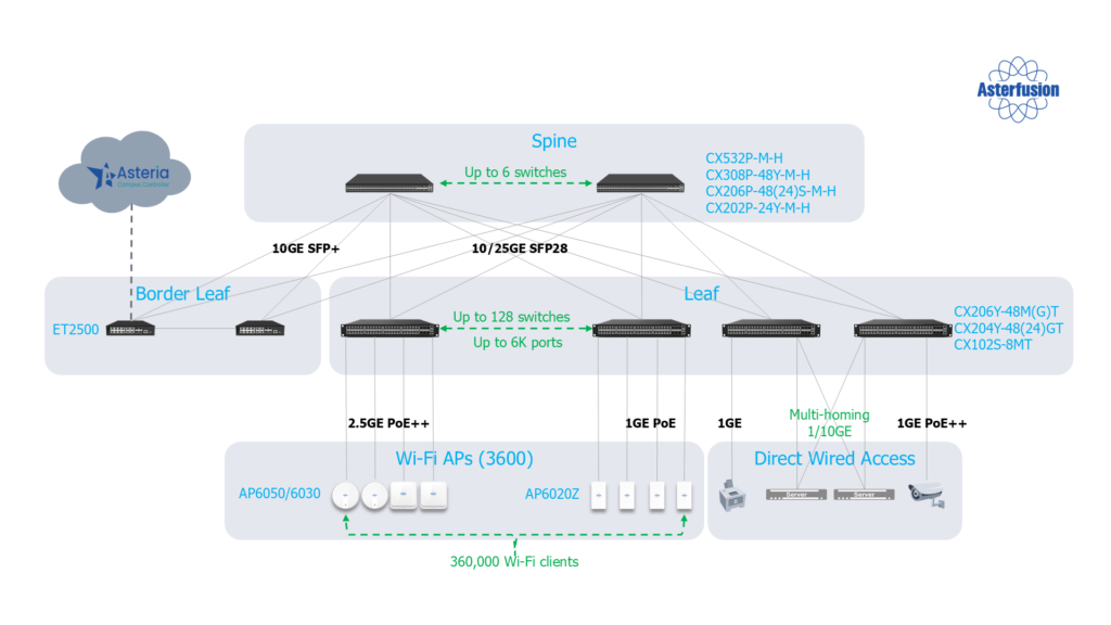
Asterfusion’s comprehensive campus network portfolio includes a wide range of devices, from access switch and aggregation switches to APs and routers. Whether 1G or 800G, every switch is powered by the feature-rich Enterprise SONiC distribution. Let’s dive deeper into the network architecture.
Scalable and Flexible Campus Network Architecture for Large-Scale Deployments
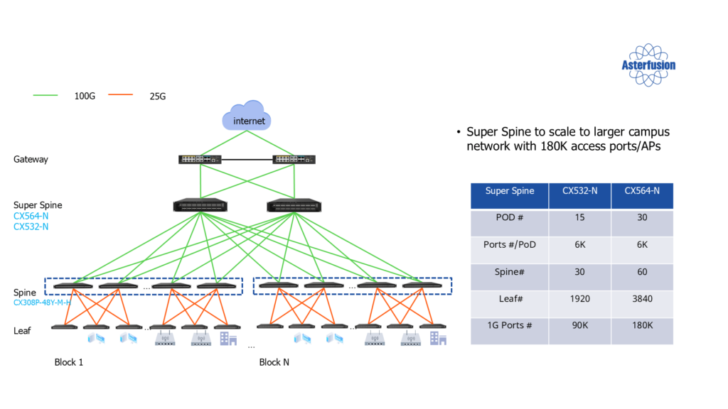
The Asterfusion campus network architecture is designed to support large-scale networks. It not only includes the traditional tier2 Leaf-Spine architecture but also supports the expansion to tier 3 networks. The overall architecture is based on a robust Clos structure, consisting of Leaf-Spine, Super-Spine, and Layer 2 aggregation networks between the Spine and Leaf. This architecture offers exceptional scalability, capable of supporting up to 180,000 interfaces for APs and endpoints, regardless of the deployment method. Such a scale effectively covers the majority of large campuses, whether in enterprises, hospitals, or schools.
Let’s begin with the routing design of the Underlay Network:
Routing Design of the Underlay Network
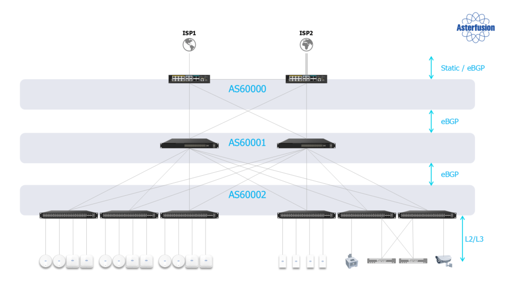
In terms of routing design, we divide the network into three Autonomous Systems (AS). The top layer is the Super-Spine, the middle layer is the Spine, and the bottom layer is the Leaf. Each layer is designed as an independent AS, with inter-layer connectivity established via eBGP. Below the Leaf layer, endpoint devices are connected to the network through 1GE ports. The key aspect is that we push Layer 3 network features, such as EVPN and BGP, to the lowest layer, enabling the functionality of a Layer 3 routing network.
IP Address Planning
The key to implementing a Layer 3 routing network lies in the proper planning of IP addresses. Since the capacity of the Marc table is limited and cannot support the infinite expansion of the campus network, it is crucial to leverage IP network aggregation. By carefully planning IP addresses, we can effectively save routing table entries. For example, multiple user IP addresses can be aggregated into a single subnet route, significantly reducing the number of entries in the routing table. However, this process needs to be closely aligned with the IP address allocation strategy. So, how can we carry out reasonable IP address allocation?
IP Address Allocation
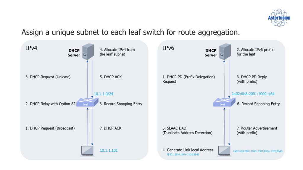
By adopting DSCP Option 82 technology, we ensure that the endpoint devices under the same Leaf switch are placed within the same subnet, enabling route aggregation and further saving routing table entries. With this allocation method, we can guarantee that, unless roaming occurs, all endpoint devices under the same Leaf switch will be concentrated in the same subnet. As a result, during subsequent routing processes, all endpoint device IP addresses can be aggregated into a single route, significantly reducing the load on host routing and saving space in the routing table.
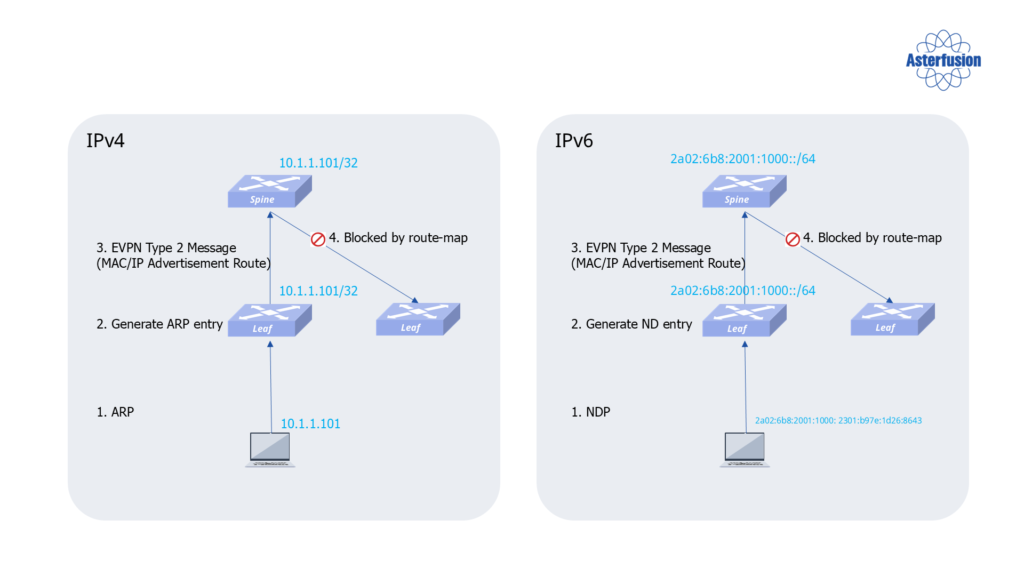
Since we are building a Layer 3 routing network for the entire system, all Layer 2 frames will be forwarded and converted into Layer 3 frames during this process. The ARP snooping mechanism plays a crucial role in this process:
ARP Snooping Mechanism
When an endpoint initiates the first ARP request, the Leaf switch listens and generates the mapping between ARP and IP addresses using the ARP snooping mechanism. This information is then propagated to the Spine devices. As a result, the host routes will only exist on the directly connected Leaf switches and Spine switches, effectively saving routing table entries on the Leaf switches.
Specifically, host routes are stored on the directly connected Leaf switch, and they can also be propagated directly to the Spine switch. Another option is to aggregate the host routes and then propagate them to the Spine switch, but these host routes will not be sent to other Leaf switches.
Through this mechanism, it can significantly reduce the number of routing table entries on the Leaf switches. Whether it’s the MAC address table or the host routing table, the Leaf switch primarily stores local routing information, thereby saving storage space. This design enhances the scalability of the network, ensuring that regardless of the network size, the information stored on the Leaf switches remains localized, with only the Spine switches holding global information.
Summarize the Routing Solution
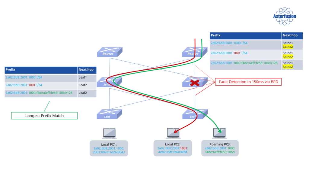
Routes are aggregated from top to bottom. The Leaf switches have default host routes, while the Spine switches maintain the entire network’s routing, including aggregated routes for non-roaming terminals and host routes for roaming terminals. The routing table of the upper-layer routers or Super-Spine switches aligns with the Spine switches, ensuring consistency.
There are two types of routes across the network:
- Non-roaming terminals: These routes are aggregated, so the routing table entries on the Spine switches are fewer.
- Roaming terminals: These terminals retain their original IP addresses. When they switch between different Leaf switches, the routes cannot be aggregated, so host routes are used. The Spine switches ensure that all roaming host routes and aggregated routes for non-roaming terminals are correctly maintained.
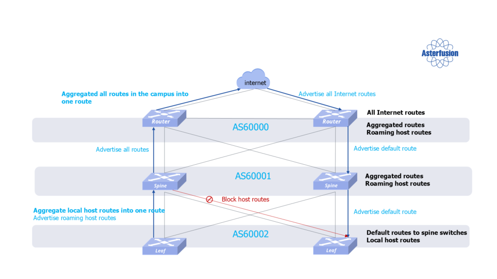
In the upper-layer routers or Super-Spine switches, the routing table is consistent with the Spine layer, which helps avoid potential routing black holes during the process.
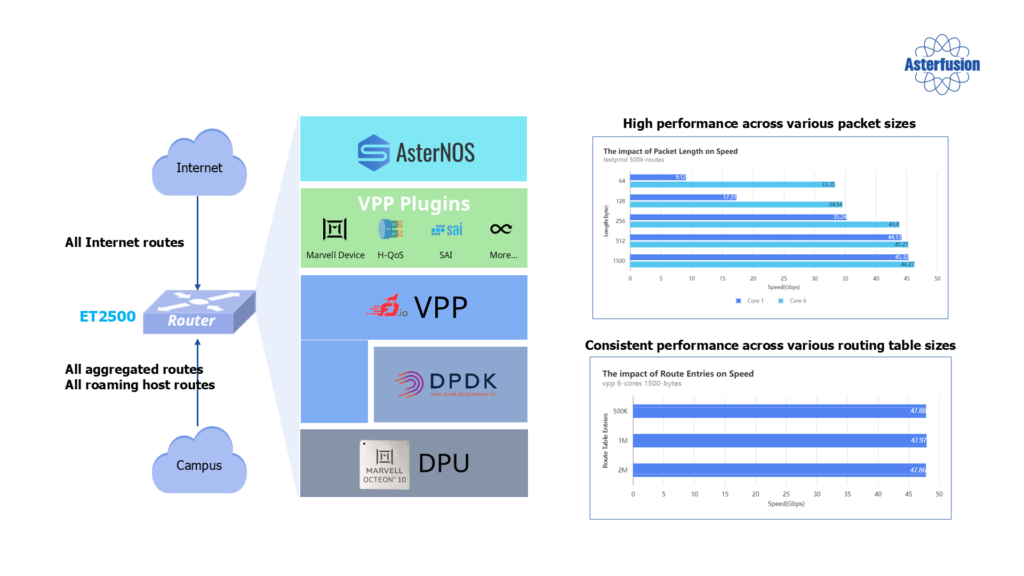
High-Performance Border Router-Asterfusion ET2500
Next, a good campus solution is incomplete without a high-performance border router:
Our border router is built on Marvell Octeon 10 DPU hardware, utilizing DPDK acceleration and VPP packet processing. With its unique architecture, Asterfusion successfully implements VPP as the data plane on the SONiC main branch. By combining SONiC with ECPM and BGP protocols, a complete network topology can be established. On a compact device, it achieves forwarding and routing performance of 48 Gbps, supports up to 2 million routes, and provides SONiC control plane, RESTful API, FRR, and Klish CLI. This enables powerful enterprise-grade routing capabilities on commercial hardware.
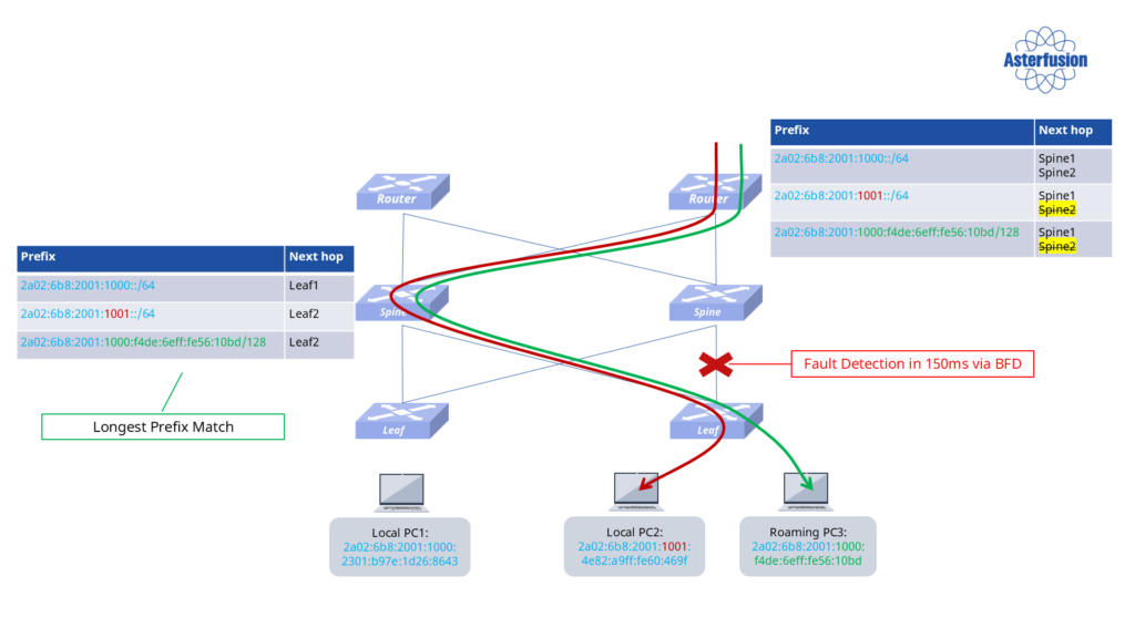
BGP Routing Convergence Capability
Our entire network utilizes the BGP routing protocol, leveraging the BFD mechanism for fast routing convergence. BGP uses BFD to monitor the link and node status, enabling rapid recovery in case of a single-link or single-node failure. The fault detection time is approximately 150 milliseconds, with adjustable performance. When a failure occurs, traffic is automatically switched to the backup switch, ensuring quick end-to-end service recovery.
Extending the Spine-Leaf Architecture
In the Spine-Leaf architecture, sometimes Layer 2 switches are added between the Spine and Leaf to extend the port capacity of the Spine switches. These Layer 2 switches do not participate in routing, EVPN, or BGP protocols; their only function is to expand port capacity. By using MCLAG technology, we ensure the reliability of the connections.
Ensuring Reliable Terminal Access with EVPN-Multihoming
So, how do we ensure the reliability of terminal access?
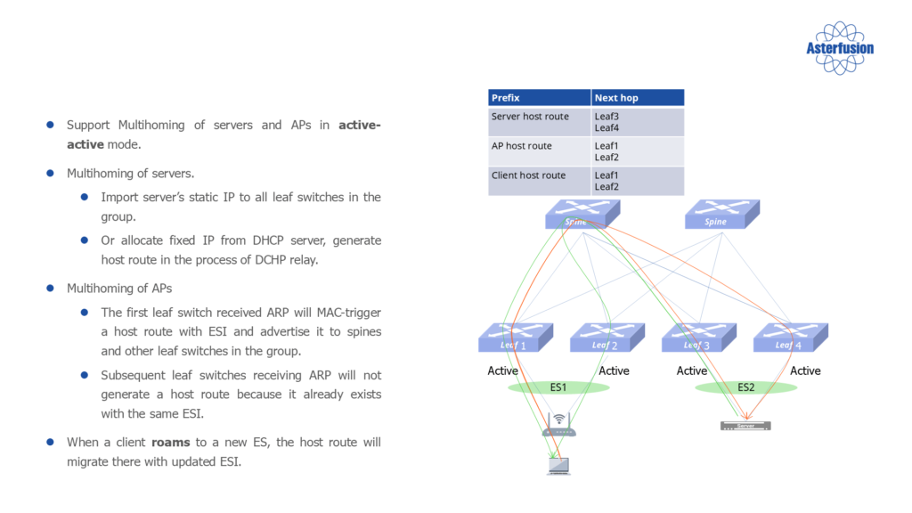
To guarantee the reliability of terminal access, Asterfusion employs EVPN-Multihoming for servers, connecting them to two Leaf switches. This active-active backup configuration, enabled by BGP multihoming, ensures that traffic continues uninterrupted in the event of a link failure. A similar setup is used for APs, which are connected to two Leaf switches to ensure continuous service even if one link fails.
We’ve covered a lot of technical detail so far, and it’s quite informative, so let’s pause for a moment.
In the next article, we’ll dive deeper into the architecture of overlay networks and explore advanced features, including key mechanisms for seamless Wi-Fi roaming and cutting-edge network security solutions. Stay tuned for more insights!


