Table of Contents
MPLS (Multiprotocol Label Switching) technology has long been used in carrier backbone and large data center networks, due to its superior traffic engineering capabilities, scalable VPN support, and rapid failure recovery features. The exciting news? Asterfusion’s full portfolio of SONiC-based open campus switches now fully supports MPLS, delivering greater flexibility, scalability, and control for your next-gen network deployments.
Model | Interface | Operation System | MPLS Support |
8x 2.5G RJ45 2x 10G SFP+ | Enterprise SONiC AsterNOS | ||
24x 1G RJ45 4x 25G/10G SFP28 | Enterprise SONiC AsterNOS | ||
48x 1G RJ45 4x 25G/10G SFP28 | Enterprise SONiC AsterNOS | ||
48x 1G RJ45 6x 25G/10G SFP28 | Enterprise SONiC AsterNOS | ||
24x 10G SFP+ 6x 100G/40G QSFP28 | Enterprise SONiC AsterNOS | ||
24x 10G SFP+ 6x 100G/40G QSFP28 | Enterprise SONiC AsterNOS | ||
16x 10G SFP+ 2x100G/40G QSFP28 | Enterprise SONiC AsterNOS | ||
24x 25G SFP28 2 x 100G/40G QSFP28 | Enterprise SONiC AsterNOS |
What is MPLS (Multiprotocol Label Switching)?
MPLS (Multiprotocol Label Switching) is an IP (Internet Protocol) backbone network technology. MPLS introduces connection-oriented label switching concepts to connectionless IP networks, combining Layer 3 routing technology with Layer 2 switching technology to fully leverage the flexibility of IP routing and the simplicity of Layer 2 switching.
MPLS is not a service or application but rather a tunneling technology. This technology not only supports multiple upper-layer protocols and services but also provides certain guarantees for information transmission security.
MPLS (Multiprotocol Label Switching) standards are mainly developed and maintained by IETF (Internet Engineering Task Force)

MPLS networks primarily consist of the following elements:
- Network devices supporting MPLS functionality are called LSRs (Label Switching Routers), which are the basic components of MPLS networks. A network area composed of a series of connected LSRs is called an MPLS domain.
- LSRs inside the MPLS domain are called Core LSRs. If all adjacent nodes of an LSR run MPLS, then that LSR is a Core LSR.
- LSRs located at the edge of the MPLS domain that connect to other networks are called LERs (Label Edge Routers). If an LSR has one or more adjacent nodes that do not run MPLS, then that LSR is an LER.
In MPLS networks, LSPs can be established between any two LERs to forward packets entering the MPLS domain, potentially traversing multiple Core LSRs. Therefore, the Ingress and Egress of an LSP are LERs, while Transit nodes are Core LSRs.
Why Do We Use SONiC Network Switch with MPLS?
With the rapid development of IP technology, Internet data has grown exponentially. However, due to hardware technology limitations, IP technology based on longest-match algorithms must use software for route lookups, resulting in poor forwarding performance. Therefore, IP forwarding performance became the bottleneck limiting network development at that time. To adapt to network evolution, MPLS technology emerged, significantly improving the forwarding speed of routing devices in IP networks.
Asterfusion’s SONiC-based campus switch devices now support MPLS, bringing carrier-grade network capabilities to enterprise and multi-tenant campus networks. By extensively integrating mature MPLS features with the open, programmable SONiC architecture, we enable customers to build simplified Layer 3 backbone networks, implement large-scale VPN isolation solutions, and achieve efficient interconnection across campuses and sites.
How Does Multi-protocol Label Switching Work?
As MPLS becomes increasingly relevant in modern business and campus networks, it is important to understand its fundamental concepts.
MPLS Basic Concepts
Forwarding Equivalence Class
FEC (Forwarding Equivalence Class) is an important concept in MPLS. MPLS groups packets with the same characteristics (such as identical destinations or service levels) into a class called FEC. Packets belonging to the same FEC receive identical treatment in the MPLS network.
Label
A label is a fixed-length identifier with only local significance, used to uniquely identify the FEC to which a packet belongs. One label can only represent one FEC.
The Layer 2 type identifier for MPLS is: Type=MPLS label switched packet (0x8847).

A label consists of four fields:
- Label: 20bit label value field.
- Exp: 3bit field for extension, now commonly used for CoS (Class of Service). When devices experience congestion, higher-priority packets are transmitted first. To avoid ambiguity, RFC5462 redefined this field as Traffic Class.
- S: 1bit bottom-of-stack identifier. MPLS supports multiple label layers (label nesting). When S=1, it indicates the bottom-most label.
- TTL: 8bit field with the same meaning as TTL (Time To Live) in IP packets.
Label Switching Router
LSR (Label Switching Router) is a device with label distribution and label switching capabilities, serving as the basic element in MPLS networks.
Label Switched Path
The path that packets belonging to the same FEC traverse through the MPLS network is called an LSP (Label Switched Path).
An LSP is a unidirectional packet forwarding path. On an LSP, adjacent LSRs along the data transmission direction are called upstream LSR and downstream LSR, respectively.

As shown in the figure, LSR B is the downstream LSR of LSR A, and correspondingly, LSR A is the upstream LSR of LSR B.
Label Forwarding Information Base
Similar to the FIB (Forwarding Information Base) in IP networks, in MPLS networks, when an LSR receives a labeled packet, it queries the LFIB (Label Forwarding Information Base) to obtain the corresponding label operation type, outgoing label value, next hop, etc., to determine how to forward the packet.

Example:
- When a packet with label 30 arrives, the router replaces it with label 40 and forwards it to next hop 192.168.1.2 through interface GigabitEthernet0/1.
- When a packet with label 40 arrives, the router pops the label (Null) and forwards it to next hop 10.0.0.1 through interface Serial0/0.
- When a packet with label 50 arrives, the router replaces it with label 60 and forwards it to next hop 192.168.2.1 through interface GigabitEthernet0/2.
Control Plane and Forwarding Plane

Control Plane: Responsible for generating and maintaining routing information and label information.
- RIB (Routing Information Base): Generated by IP routing protocols, used for route selection.
- LDP (Label Distribution Protocol): Responsible for label allocation, establishment of label forwarding information tables, and establishment/teardown of label switched paths.
- LIB (Label Information Base): Generated by label distribution protocols, used for managing label information.
Forwarding Plane: Also known as the Data Plane, responsible for forwarding regular IP packets and MPLS-labeled packets.
- FIB (Forwarding Information Base): Generated by extracting necessary routing information from RIB, responsible for forwarding regular IP packets.
- LFIB (Label Forwarding Information Base): Also called the label forwarding table, established by label distribution protocols on LSRs, responsible for forwarding MPLS-labeled packets.
LDP
LDP is a crucial label distribution control protocol in the MPLS architecture, responsible for FEC classification, MPLS label allocation, and dynamic establishment and maintenance of LSPs. It defines various messages and related processing procedures during the label distribution process. Through the LDP protocol, LSRs can directly map network layer routing information to data link layer LSP switching paths, enabling dynamic LSP establishment at the network layer.
LDP offers advantages including simple networking and configuration, support for route topology-driven LSP establishment, and support for high-capacity LSPs.
LDP Session Establishment
LDP has four types of session messages:
- Discovery Messages: Used to advertise and maintain the presence of LSRs in the network.
- Session Messages: Used to establish, maintain, and terminate sessions between LDP peers, including Initialization and Keepalive messages.
- Advertisement Messages: Used to create, modify, and delete label mappings for FECs.
- Notification Messages: Used to provide advisory messages and error notifications.
To ensure reliable transmission of LDP messages, except for discovery messages, which use UDP, LDP session messages, advertisement messages, and notification messages all use TCP transport. LDP sessions are triggered by the exchange of Hello messages between two LSRs. Using the following diagram as an example, the LDP session establishment process is described:

- Hello Message Exchange: Two LSRs exchange Hello messages with each other. Hello messages carry transport addresses, which are used by both parties to establish the LDP session. The party with the larger transport address acts as the active party and initiates the TCP connection establishment. In the figure, LSR A acts as the active party initiating the TCP connection, while LSR B acts as the passive party waiting for the connection.
- TCP Connection and Initialization: After successful TCP connection establishment, the active party LSR A sends an Initialization message to negotiate LDP session-related parameters, including LDP protocol version, label distribution method, Keepalive timer value, maximum PDU length, and label space.
- Parameter Negotiation Response: After receiving the Initialization message, if passive party LSR B cannot accept the related parameters, it sends a Notification message to terminate LDP session establishment. If LSR B can accept the parameters, it sends an Initialization message and simultaneously sends a Keepalive message to active party LSR A.
- Final Confirmation: After receiving the Initialization message, if active party LSR A cannot accept the related parameters, it sends a Notification message to passive party LSR B to terminate LDP session establishment. If it can accept the parameters, it sends a Keepalive message to passive party LSR B.
When both parties receive Keepalive messages from their peers, the LDP session is successfully established.
MPLS Label Distribution Process
LSP Establishment
MPLS must pre-allocate labels for packets and establish an LSP before packet forwarding can occur.
Labels are allocated by downstream LSRs and distributed in the downstream-to-upstream direction. Downstream LSRs perform FEC classification based on the IP routing table, allocate labels according to FECs, and advertise them to upstream LSRs to establish label forwarding tables and LSPs.
Egress LSR

R4 is directly connected to network segment 192.168.1.1/24. R4 will proactively allocate a label (such as 1041) for routes reaching this network segment and actively advertise the label mapping to LDP peers R2 and R3 through LDP protocol messages.
Transit LSR

Taking R2 as an example, in its routing table, the next hop for route 192.168.1.1/24 is R4. When it receives a label mapping advertisement for 192.168.4.0/24 from R4, since this advertisement comes from a downstream LDP neighbor, it triggers R2 to allocate its own label 1021 for this route and advertise the label mapping to LDP neighbor R1. The same principle applies to R3.
Ingress LSR

After R1 receives label mapping advertisements for route 192.168.1.1/24 from LDP neighbors R2 and R3, it stores both labels. However, since the next hop to reach 192.168.1.1/24 in its own routing table is R2, it will currently only use label 1021 advertised by R2.
MPLS Forwarding Process
Basic Concepts
The following concepts are involved in the MPLS basic forwarding process:
Label operation types include Label Push, Label Swap, and Label Pop, which are the fundamental actions of label forwarding.
- Push: When an IP packet enters the MPLS domain, the MPLS edge device inserts a new label between the Layer 2 header and IP header; or when an MPLS intermediate device adds a new label to the top of the label stack as needed (label nesting encapsulation).
- Swap: When a packet is forwarded within the MPLS domain, the top label of the MPLS packet is replaced with the label allocated by the next hop according to the label forwarding table.
- Pop: When a packet leaves the MPLS domain, the label is stripped from the MPLS packet.
- At the last hop node, the label has no useful value. In this case, the PHP (Penultimate Hop Popping) feature can be utilized to pop the label at the penultimate hop node, reducing the burden on the last hop. The last hop node directly performs IP forwarding or next-layer label forwarding.
- By default, devices support the PHP feature. Egress nodes supporting PHP allocate label value 3 to the penultimate hop node.
Processing Procedure
LSRs process packets mainly based on FTN, NHLFE, and ILM.
- FTN (FEC-to-NHLFE): Used when an LSR receives an IP packet and needs to perform MPLS forwarding. FTN exists only at Ingress nodes. FTN includes: Tunnel ID, FEC-to-NHLFE mapping information.
- NHLFE (Next Hop Label Forwarding Entry): Used when an LSR performs MPLS forwarding on packets (MPLS or IP packets). NHLFE exists at Ingress and Transit nodes. NHLFE includes: Tunnel ID, outgoing interface, next hop, outgoing label, label operation type, and other information.
- ILM (Incoming Label Map): Used to guide MPLS packet forwarding (MPLS or IP forwarding). ILM exists only at Transit and Egress nodes. ILM includes: Tunnel ID, incoming label, incoming interface, label operation type, and other information.
Ingress LSR Processing
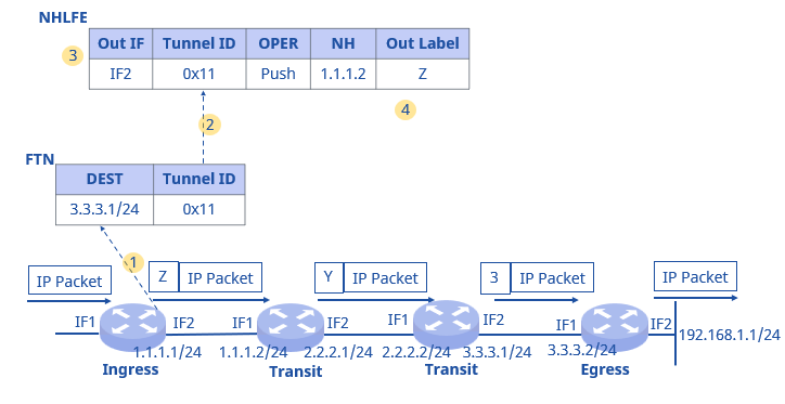
When an IP packet enters the MPLS domain:
- The Ingress LSR checks the FTN table to see if the Tunnel ID value corresponding to the destination IP address is 0x0 (if the Tunnel ID value is 0x0, it enters the normal IP forwarding process).
- If the Tunnel ID value is not 0x0, it finds the corresponding NHLFE entry based on the Tunnel ID in the FTN table, associating the FIB entry with the NHLFE entry.
- By examining the NHLFE entry, it obtains the outgoing interface, next hop, outgoing label, and label operation type.
- It pushes the outgoing label into the IP packet, processes the TTL, and then sends the encapsulated MPLS packet to the next hop.
Transit LSR Processing

When a Transit LSR receives the MPLS packet:
- The Transit LSR checks the corresponding ILM table based on the MPLS label value to obtain the Tunnel ID.
- It finds the corresponding NHLFE entry based on the Tunnel ID in the ILM table.
- By examining the NHLFE entry, it obtains the outgoing interface, next hop, outgoing label, and label operation type. If the label operation type is Swap, it swaps the label.

When the penultimate hop‘s Transit LSR receives the MPLS packet:
- The Transit LSR checks the corresponding ILM table based on the MPLS label value to obtain the Tunnel ID.
- It finds the corresponding NHLFE entry based on the Tunnel ID in the ILM table.
- By examining the NHLFE entry, since the label value is 3, it performs the PHP operation, pops label Y, and continues forwarding the packet to the Egress.
Egress LSR Processing

The Egress node receives the IP packet and directly forwards it to destination 192.168.1.1/24 according to the corresponding IP routing table.
MPLS Security Mechanisms
MD5
MD5 (Message-Digest Algorithm 5) is an international standard digest cryptographic algorithm defined by relevant standards. The typical application of MD5 is to calculate a corresponding message digest for a piece of information, thereby preventing information tampering. The MD5 message digest is generated through an irreversible string transformation algorithm with unique results. Therefore, regardless of any changes to the information content during transmission, recalculation will produce a different message digest, allowing the receiving end to determine that an incorrect packet has been received.
LDP MD5 authentication is performed before TCP transmission: Before LDP messages are sent via TCP, a unique message digest is appended after the TCP header. This message digest is calculated using the MD5 algorithm with the TCP header, LDP message, and user-configured password as the original information.
When the receiving end receives this TCP packet, it first extracts the packet’s TCP header, message digest, and LDP message, then calculates a message digest using MD5 with the TCP header, LDP message, and locally stored password. It then compares this with the message digest carried in the packet to verify whether the packet has been tampered with.
GTSM
GTSM (Generalized TTL Security Mechanism) in practical applications primarily serves to protect the control plane built on the TCP/IP layer from CPU-utilization (CPU overload) attacks. When applied to LDP, GTSM is applied to various LDP message packets to prevent attacks that cause CPU-utilization when the LDP protocol receives large quantities of spoofed packets.

As shown in the figure, LSR1-LSR5 are core routers in the backbone network. When LSRA is indirectly connected to core routers through other devices, LSRA may forge LDP-related packets between LSR1-LSR5 for attack purposes.
When LSRA accesses through other devices, the TTL value carried in forged packets is considered non-forgeable, which is the premise of GTSM.
GTSM policies are configured on LSR1-LSR5 for each possible neighbor: For example, on LSR5, packets sent by LSR2 are configured with a valid hop count of 1-2 and valid TTL values of 254-255. When forged packets sent by LSRA reach LSR5, due to traversing multiple intermediate devices, the TTL becomes smaller than the preset valid range, allowing LSR5 to directly discard the forged packets and avoid attacks.
MPLS TTL Processing Modes
MPLS labels contain an 8-bit TTL field with the same meaning as the TTL field in IP headers. MPLS TTL processing is used not only to prevent routing loops but also to implement Traceroute functionality.

When IP packets traverse MPLS networks, at the ingress node, the IP TTL is decremented by 1 and mapped to the MPLS TTL field. Thereafter, packets are processed in the MPLS network according to standard TTL processing methods. At the egress node, the MPLS TTL is decremented by 1 and then mapped to the IP TTL field.
MPLS QoS
MPLS DiffServ
MPLS-based DiffServ is implemented by combining DS or PRI allocation with the MPLS label allocation process.

MPLS DiffServ maps the EXP field of MPLS packets to DiffServ PHB (Per-Hop Behavior), with LSRs using the EXP field to guide packet forwarding. MPLS DiffServ provides two solutions:
- E-LSP (EXP-Inferred-PSC LSP): LSPs where PHB is determined by EXP. This method is suitable for networks supporting fewer than 8 PHBs, where specified DSCP (Differentiated Service Code Point) or 802.1p values are mapped to specific EXP values, identifying specific PHBs. During forwarding, packets are forwarded based on labels, while EXP determines scheduling and drop priority at each LSR hop. Therefore, a single LSP can carry 8 different PHB classes of traffic, differentiated through the EXP field in the MPLS header. EXP can be directly configured by users or mapped directly from packet DSCP or 802.1p values. This method requires no signaling protocol to convey PHB information, has high label utilization, and maintains an easily manageable state.
- DiffServ PHB to EXP Mapping Table:
| PHB Behavior | EXP Priority |
| BE | 0 |
| AF1 | 1 |
| AF2 | 2 |
| AF3 | 3 |
| AF4 | 4 |
| EF | 5 |
| CS6 | 6 |
| CS7 | 7 |
- L-LSP (Label-Only-Inferred-PSC LSP): LSPs where PHB is determined jointly by label and EXP. This method is suitable for networks supporting any number of PHBs. During forwarding, labels are used not only to determine forwarding paths but also scheduling behavior at LSRs, while EXP bits determine packet drop priority. Since service flow types are differentiated through labels, different LSPs must be established for different flows. This method requires more labels and consumes significant system resources.
DiffServ Domains

As shown, DiffServ domains can be divided into MPLS DiffServ domains and IP DiffServ domains.
In the E-LSP solution, at MPLS network edges, MPLS DiffServ provides coordinated management and scheduling between the two DiffServ domains, completing bidirectional mapping between DSCP or 802.1p and EXP.

As illustrated, in MPLS networks, packet forwarding is based on the EXP field of MPLS packets, providing different service quality levels to customers.
When MPLS packets enter devices (P), traffic classification is performed, uniformly mapping the EXP carried by packets to internal service levels and drop priorities. After traffic classification, QoS implementation methods such as traffic shaping, traffic policing, and congestion avoidance are identical to those in IP networks. When packets exit devices (P), the original EXP carried by packets is preserved.
Uniform Mode
Priority markings for packets in IP and MPLS networks are uniformly defined, meaning both networks’ priority markings are globally valid. At Ingress, packets are labeled with DSCP or 802.1p mapped to EXP. If the EXP field value changes within the MPLS network, it affects the PHB used after the packet leaves the MPLS network. At the egress node, EXP is mapped back to DSCP or 802.1p.

As shown in the L3VPN example, at PE_1, the packet’s IP DSCP value is mapped to both Outer MPLS EXP and Inner MPLS EXP values (set to 5). At P_2, the outer MPLS label is popped and the Inner MPLS EXP value becomes the Outer MPLS EXP value. At PE_2, through the mapping relationship, the packet’s IP DSCP value becomes 46.
Pipe Mode
At Ingress, the EXP value of MPLS labels pushed onto packets can be user-specified. If the EXP field value changes within the MPLS network, it is only valid within the MPLS network. At Egress, packets select PHB based on the EXP field value. When packets leave the MPLS network, the previously carried DSCP or 802.1p values remain valid.

As shown in the L2VPN example, at PE_1, both Outer MPLS EXP and Inner MPLS EXP values are set to 1. At PE_2, the original packet’s 802.1p value is not changed, and packets select PHB based on the Inner MPLS EXP value.
MPLS VPN
MPLS VPN refers to the technology that utilizes MPLS to construct VPNs over IP backbone networks. The essence of VPN is to transmit business data over public networks as if using a private dedicated network. This requires establishing a tunnel over the public network, allowing data packets to reach their destination directly through the tunnel, thereby achieving the effect of a private dedicated network. In summary, MPLS VPN uses LSPs established by MPLS as public network tunnels to transmit private network business data.
L2VPN
VPWS
VPWS (Virtual Private Wire Service) is a point-to-point L2VPN service.

VPWS functional components include the following parts:
- AC (Attachment Circuit): An independent link or circuit connecting CE and PE. AC interfaces can be physical or logical interfaces. AC attributes include encapsulation type, Maximum Transmission Unit (MTU), and interface parameters specific to link types.
- PW (Pseudo Wire): A logical connection between two PE nodes.
- Tunnel (Network Tunnel): Used for transparent transmission of service data.
- PW Signal: PW signaling protocol used to negotiate PWs.
As shown in the VPWS basic architecture diagram, using the VPN1 packet flow from CE1 to CE3 as an example, the basic data flow is as follows:
- CE1 sends user packets to PE1 through AC.
- PE1 receives packets and selects the PW for forwarding.
- PE1 generates two layers of MPLS labels based on PW forwarding entries (private network label identifies PW, public network label traverses the tunnel to reach PE2).
- User packets reach PE2 through the public network tunnel, and the system pops the private network label (the public network label is popped at the penultimate hop at the P device).
- PE2 selects the AC for forwarding packets and forwards user packets to CE3.

During VPWS forwarding, label stack changes are shown in the diagram above:
- L2 PDU (Protocol Data Unit) represents link-layer packets
- T represents Tunnel label
- V represents Virtual Circuit (VC) label
- T’ represents outer label replacement during forwarding
VPLS
VPLS (Virtual Private LAN Service) is a point-to-multipoint L2VPN service.

As shown in the diagram, the entire VPLS network functions like a switch, establishing virtual connections (PWs) between various sites of each VPN through MPLS tunnels and transparently transmitting user Layer 2 packets between sites through PWs. For PE devices, they learn source MACs while forwarding packets and establish MAC forwarding entries, completing the mapping relationship between MAC addresses and user access interfaces (AC interfaces) and pseudo wires (PWs).
Using the packet flow from CE1 to CE3 in VPN1 as an example, the basic data flow is explained:
- CE1 sends user Layer 2 packets, accessing PE1 through AC links.
- PE1 receives packets, and the Forwarder selects the PW for forwarding.
- PE1 generates two layers of labels based on PW forwarding entries and tunnel information (inner private network label identifies PW, outer public network label traverses tunnel to reach PE3).
- Layer 2 packets reach PE3 through the public network tunnel, and the system pops the private network label.
- PE3’s Forwarder selects the AC for forwarding packets and forwards CE1’s Layer 2 packets to CE3.
Note: The Forwarder is equivalent to the VPLS forwarding table.
VPLS Implementation Process:

Note: VSI (Virtual Switch Instance) maps attachment circuits to various pseudo wires. Each VSI provides separate VPLS services, performing Layer 2 packet forwarding based on MAC addresses and VLAN Tags. VSI implements Ethernet bridge functionality and can terminate PWs.
PE devices in VPLS networks contain control plane and data plane:
- VPLS PE Control Plane primarily implements PW establishment functionality, including:
- Member Discovery: The process of finding all other PEs in the same VSI. Can be implemented through manual configuration or automatic protocol completion. Protocol-based automatic discovery is called “auto-discovery.”
- Signaling Mechanism: The task of establishing, maintaining, and tearing down PWs between PEs in the same VSI is completed by signaling protocols, including LDP and BGP.
- VPLS PE Data Plane primarily implements PW data forwarding functionality, including:
- Encapsulation: After receiving Ethernet frames from CEs, PEs first encapsulate them before sending to packet-switched networks.
- Forwarding: Determines how to forward packets based on which interface received the packet and the destination MAC address.
- Decapsulation: After receiving Ethernet frames from packet-switched networks, PEs first decapsulate them before forwarding to CEs.
MPLS L3VPN
BGP/MPLS L3VPN (referred to as MPLS L3VPN): A Layer 3 VPN technology built on BGP and MPLS foundations. It leverages the BGP protocol for VPN route advertisement, uses VPN instances to achieve service isolation, and implements VPN packet forwarding through MPLS label switching technology.

Packet Forwarding Process
- CE1 sends an IP packet to the Ingress PE.
- Ingress PE receives the VPN data packet from the interface bound to the VPN instance and performs the following operations:
- Looks up the corresponding VPN forwarding table based on the RD of the bound VPN instance.
- Matches the destination IPv4 prefix and finds the corresponding Tunnel-ID.
- Applies the corresponding label (I-L) to the packet and locates the tunnel based on the Tunnel-ID.
- Sends the packet through the tunnel. In this example, the tunnel is an LSP and applies a public network (outer) MPLS label header (O-L1).
- The packet traverses the backbone network with two label layers. Each P device in the backbone network performs outer label switching on the packet.
- Egress PE receives the packet carrying two label layers and passes it to the MPLS protocol for processing. The MPLS protocol removes the outer label.
- Egress PE strips the inner label at the bottom of the stack.
- Egress PE sends the packet to CE2 through the corresponding outbound interface. At this point, the packet is a pure IP packet.
The packet has successfully been transmitted from CE1 to CE2. CE2 forwards the packet to its destination following the standard IP forwarding process.
Inter-AS VPN Option A
Inter-AS VPN Option A is the application of basic IPv4 L3VPN in inter-domain environments. ASBRs do not need to run MPLS between each other, nor do they require special configuration for inter-domain connectivity. In this approach, ASBRs from two ASes are directly connected, with each ASBR also serving as a PE in its respective autonomous system. Each ASBR treats the peer ASBR as its own CE device, creating VPN instances for each VPN and advertising IPv4 routes to the peer using EBGP.

As shown in the diagram, for ASBR1 in AS100, ASBR2 in AS200 is merely a CE device; similarly, for ASBR2, ASBR1 is just an attached CE device. In the figure, VPN LSP (Label Switched Path) represents the private network tunnel, while LSP represents the public network tunnel.
Inter-AS VPN Option B
In the Inter-AS VPN Option B solution, ASBRs receive all inter-domain VPN-IPv4 routes from both within their domain and from external domains, then redistribute these VPN-IPv4 routes. However, in basic MPLS VPN implementations, PEs only retain VPN routes that match the VPN Target of local VPN instances. Through special processing of labeled VPN-IPv4 routes, ASBRs are configured to bypass VPN Target matching and store all received VPN routes, regardless of whether there are matching local VPN instances.

As illustrated, in Inter-AS VPN Option B, two ASBRs exchange labeled VPN-IPv4 routes received from PE devices in their respective ASes through MP-EBGP. In the figure, VPN LSP represents the private network tunnel, while LSP represents the public network tunnel.
Comparison of Option A vs Option B
| Dimension | Option A | Option B |
| Implementation Principle | ASBRs treat each other as CEs, exchanging IPv4 routes via EBGP without MPLS label encapsulation | ASBRs exchange VPNv4 routes via MP-EBGP with MPLS label encapsulation |
| Data Transmission Format | IPv4 packets | MPLS-labeled packets |
| Intermediate Device Support | Intermediate devices can directly identify and process packet characteristics (e.g., firewalls) | Intermediate devices may not directly identify labeled packets |
| Performance Requirements | Relatively lower performance due to unlabeled packets with slightly lower forwarding efficiency | Higher performance through more efficient LSP forwarding |
| Configuration Complexity | Relatively simple configuration; no special configuration required between ASBRs | More complex configuration; ASBRs require MPLS enablement and MP-EBGP configuration |
| Route Exchange | VPNv4 routes are exchanged between ASBRs with label switching | Suitable for scenarios with unified VRF planning and high-performance requirements |
| Applicable Scenarios | Suitable for scenarios with non-unified VRF planning where intermediate devices need to identify packet characteristics | Better scalability through label switching, enabling more flexible network expansion |
| Network Scalability | Relatively poor scalability as each VPN requires individual configuration | Relatively poor scalability, as each VPN requires individual configuration |
MPLS vs Traditional Campus Network Technology Comparison
| Requirement Dimension | Traditional Solution (VLAN + QoS) | MPLS Solution |
| Network Scale | Suitable for single-building deployments with <50 devices | Suitable for cross-building campus networks with >100 devices |
| Isolation Requirements | VLAN isolation (4094 VLAN limit) | Unlimited VPN isolation |
| Fault Recovery Speed | STP convergence time: 2-50 seconds | MPLS-TP switching: <50ms |
| Multi-Cloud Access Complexity | Requires independent configuration of multiple dedicated cloud links | Single MPLS domain interfaces with multi-cloud (EVPN) |
| Hardware Cost | Standard Layer 3 switches | MPLS-capable switches |
What Network Scenarios is MPLS Suitable For?
Multi-Service Converged Large-Scale Composite Campus
Scenario Characteristics
Large enterprise headquarters, comprehensive hospitals, or university campuses with multiple business systems (office applications, research, video surveillance, IoT devices, etc.) require physical networks to support differentiated requirements for various business traffic flows.
MPLS Advantages
Service Isolation
- MPLS L3VPN Implementation: Achieves logical isolation between different departments (e.g., Finance, R&D), avoiding traditional VLAN quantity limitations (4094 limit) and supporting thousands of independent virtual networks.
Fine-Grained QoS Control
EXP Label Priority Allocation Examples:
- Video Conference Traffic → EXP=5 (Highest priority, 30% bandwidth guarantee)
- File Transfer Traffic → EXP=1 (Minimum bandwidth guarantee, pre-emptible)
- IoT Sensor Data → EXP=0 (Best-effort forwarding)
Hybrid Cloud Access Campus
Scenario Characteristics
Enterprise headquarters requiring direct access to public clouds (AWS/Azure) and private clouds. Traditional solutions require configuring multiple independent circuits, resulting in high management complexity.
MPLS Integration Solution
Unified Underlay
- Core Switch as PE Device: Campus network core switches function as PE devices, interfacing with cloud service providers through MPLS L2VPN/L3VPN
Learn more about:
How to configure MPLS on a CX-M Asterfusion Enterprise SONiC Switch?
Author:

Serena Guo
Technical Marketing Manager
Bridging R&D and Market for Open Campus Networks Asterfusion | 5+ Years at the Forefront of Campus Networking


