Table of Contents
Introduction
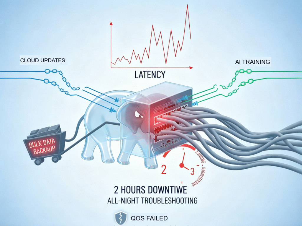
Ever had this happen? A single elephant flow from a bulk backup eats up 80% of your core switch bandwidth, bringing your data center down for hours. Cloud updates stall, AI training freezes, and you end up troubleshooting all night. If you’ve watched latency skyrocket as elephant flows crush your QoS, you know the pain.
Here’s how ARS on SONiC can fix it using flowlet switching and intelligent load distribution.
Ⅰ. Three Main Load Balancing Techniques
First, let’s look at two types of flows. The large flows mentioned earlier are known as elephant flows. Elephant flows are rare but huge, consuming massive bandwidth for long periods—think GB-level transfers during VM migration or data backups. Mice flows, on the other hand, are short, bursty, and parallel—small requests like web queries or emails.
Modern data centers mainly use three load balancing approaches: per-flow, per-packet, and flowlet-based. These methods aim to reduce congestion and make better use of bandwidth when elephant flows occur. Next, we’ll explore how each works and their trade-offs.
1. Per-flow Load Balancing
In traditional LAG or ECMP setups, a flow is identified by a hash of its five-tuple (source/destination IP, source/destination port, protocol). Flows sharing the same hash are treated as a single unit, with all packets sent over the same link.
For example, in LACP, as shown in the figure below,multiple physical links form one logical link. A flow with hash A goes entirely over Physical Link A, while a flow with hash B uses Link B.
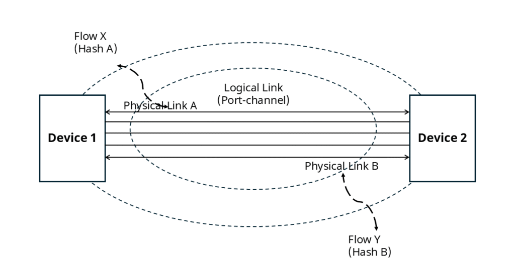
This method distributes different flows across member links while keeping packets within the same flow in order.
Known as static load balancing, it does not consider real-time link load. As a result, large elephant flows can cause congestion or packet loss on heavily loaded links.
2. Per-Packet Load Balancing
Per-packet load balancing treats each packet as an individual unit and distributes packets across multiple links.
Common algorithms are Random and Round Robin. Random distributes packets to links arbitrarily, while Round Robin ideally balances traffic by sending packets sequentially across all links.
In practice, per-packet load balancing ignores real-time link load and forwarding delays, simply distributing packets across links. It also cannot ensure in-order delivery, forcing the receiver to reorder packets. Out-of-order arrivals can cause congestion, retransmissions, and packet loss.
3. Adaptive Routing and Switching (ARS)
ARS on SONiC is essentially a flowlet load balancing and flowlet switching technique that leverages the ASIC’s hardware Auto-Load-Balancing (ALB) capabilities.
Unlike the previous two methods, ARS splits large flows into smaller sub-flows(flowlet) to distribute traffic across multiple links. By configuring an appropriate idle time, ARS can achieve near per-packet balancing without causing packet reordering.
Additionally, ARS can sense real-time link quality and proactively perform traffic path allocation and reallocation, reducing congestion and improving overall network bandwidth utilization.
Next, let’s look at how ARS on SONiC works.
Ⅱ. How ARS on SONiC Works
Here are a few related concepts to understand:
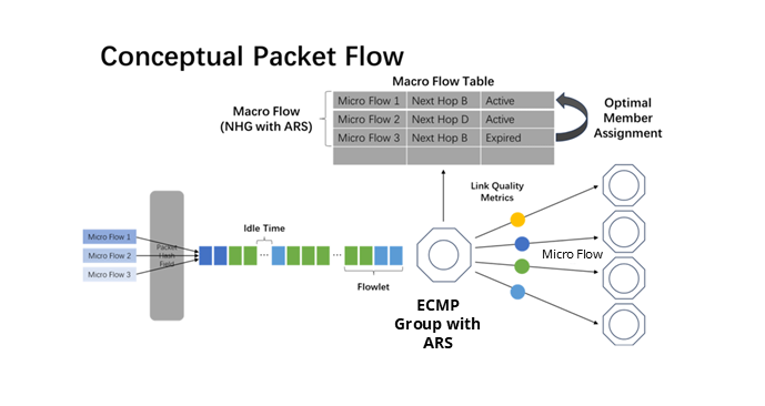
- Micro Flow: A set of packets sharing the same five-tuple (source IP, destination IP, source port, destination port, protocol).
- Macro Flow: A group of micro flows that share the same hash value.
- Idle Time: A period of inactivity within a macro flow where no packets are transmitted.
- Flowlet: A sequence of consecutive packets (or micro flows) within a macro flow that is separated by idle time.
1. Elephant Flows into Flowlets
Flowlets are the basic unit of load balancing in ARS. When your network has an elephant flow (a macro flow) composed of multiple micro flows with massive traffic, how does ARS handle it?
ARS on SONiC splits the micro flows within your elephant flow into separate flowlets for flowlet switching and efficient flowlet load balancing. The criterion for classification is the idle time: if the interval between two micro flows exceeds the configured idle time, they are considered two different flowlets. In this way, a single elephant flow is broken down into multiple smaller, schedulable flowlets.
2. Link Metrics
After splitting an elephant flow into smaller flowlets, how do we decide which path to forward them on? In Asterfusion, ARS on SONiC measures link metrics using both the control plane and the ASIC. The key metrics monitored are Port Bandwidth, Port Utilization and Forwarding Latency
Port Bandwidth: For ports with ARS enabled, the control plane normalizes the line-rate speeds and programs this information into the ASIC. The normalization uses a simple scaling factor based on a 10G base rate.
This enables the ASIC to proportionally calculate each link’s capacity for distributing flowlets, ensuring dynamic load balancing, preventing link overload, and improving overall bandwidth utilization.
Port Utilization: Port bandwidth utilization indicates the real-time traffic load on the port. The ASIC samples the flow rate, compares it with the port’s line rate, and calculates utilization. An Exponentially Weighted Moving Average (EWMA) is then applied to derive the port’s average load, allowing the link to dynamically adapt to varying traffic patterns.
Forwarding Latency: The forwarding latency of a link is reflected by the depth of its port queues. The ASIC samples the port queue depth and uses EWMA to compute historical load trends.
Together, these three metrics define the real-time quality of a link at any given moment.
3. Dynamic Path Selection
Flowlet adjustment follows a simple rule: when a micro flow becomes inactive (e.g., a new flow arrives), the ASIC reassigns it to the optimal link based on the above link metrics, enhancing load balancing efficiency and active flow performance.
The ASIC maintains a macro flow table that maps each micro flow to its egress interface, known as Flowlet Entries.
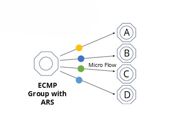
For example, in an ECMP scenario, suppose the last micro flow of a flowlet, Micro flow 2, is assigned to path D, and after a time interval T (where T > Idle Time), the next micro flow, Micro flow 3, arrives. Since T > Idle Time, the ASIC considers the previous flowlet as completed, and the path mapping of that flowlet to path D has expired.
The subsequent micro flow, Micro flow 3, is thus identified as a new flowlet and is in an inactive state. This triggers an active path selection, assigning Micro flow 3 to another available link, such as path A.
Ⅲ. Application Scenarios
Let’s look at a real-world scenario to see how ARS handles elephant flows.
1. Load Balancing Scenario
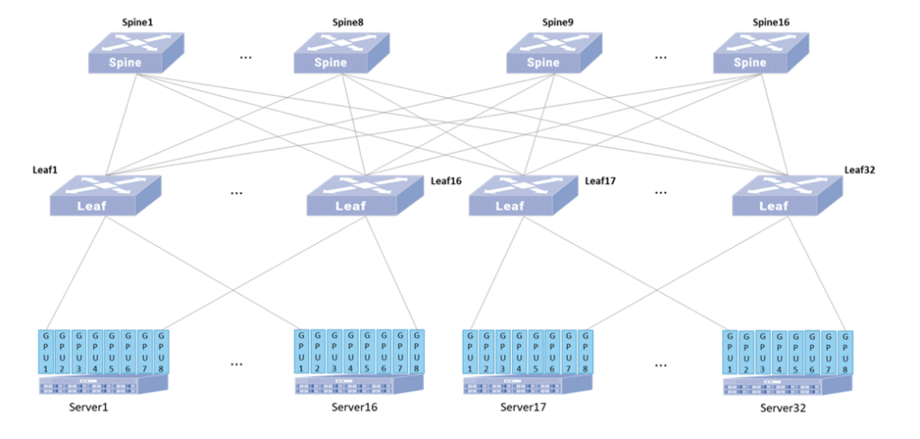
The above diagram illustrates a typical AIDC backbone network topology.
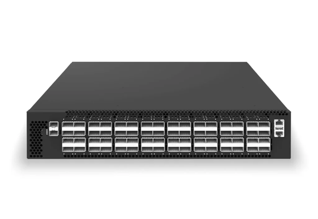
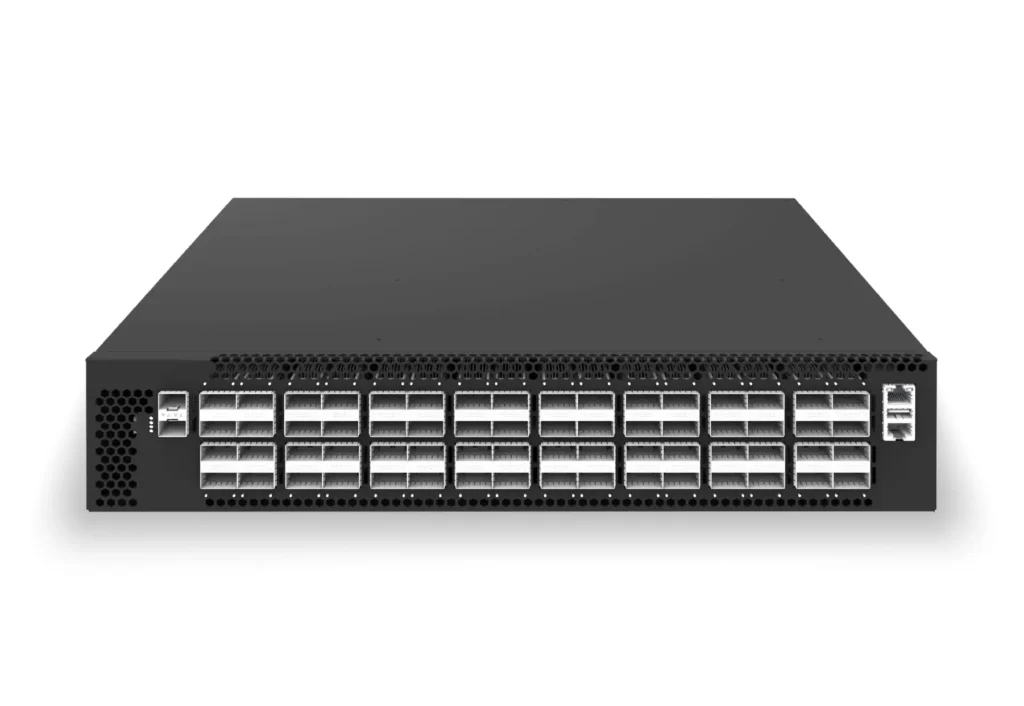
In this example, the network has 32 servers with 8 GPUs each (256×400G NICs), built on a two-tier Clos AIDC backbone using Asterfusion CX864E-N Spine and Leaf switches. A 1:1 downlink-to-uplink ratio ensures high throughput and avoids asymmetric bandwidth issues.
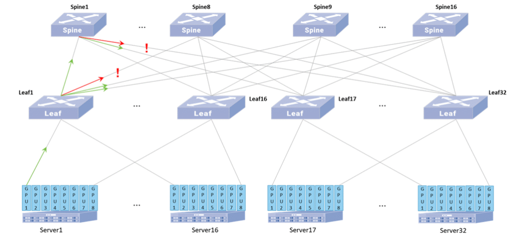
Now, suppose Server1’s GPU1 communicates with Server17’s GPU1, traditional load balancing may send large elephant flows to the same Spine (e.g., Spine1), ignoring real-time path conditions. This can congest Leaf1’s uplink and cause packet loss.
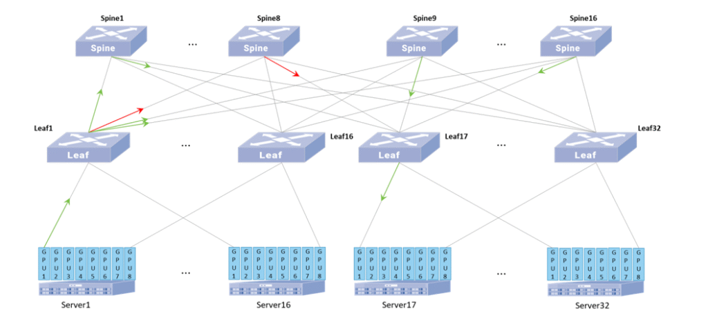
After enabling ARS on the CX864E-N:
Suppose the uplink from Leaf1 to Spine8 becomes congested. When a new Flowlet arrives, Leaf1’s ASIC reduces the number sent to the congested Spine8 and shifts more traffic to other available Spines.
From Spine1’s downlink perspective, its ASIC similarly reduces Flowlets toward congested Leaf32 links and directs more traffic to less congested, higher-quality paths.
This autonomous Leaf and Spine behavior alleviates network-wide congestion and boosts overall bandwidth utilization.
2. Failure Recovery
With traditional load balancing, ECMP link failures require coordination between the control plane and ASIC, making recovery speed dependent on the control plane’s response time.
With ARS enabled, the ASIC monitors port status in real time and instantly reallocates traffic upon link failure, enabling autonomous path switching and rapid convergence. The control plane only updates the global routing table afterward, without affecting real-time forwarding.
Ⅳ. Conclusion
With ARS on SONiC, the shortcomings of traditional static load balancing are addressed. For comparison, see the table below:
| Load Balancing Method | Issues | ARS on SONiC | Impact Solved |
| Per-flow ECMP / LAG | Elephant flows concentrate on a single link, causing congestion; no awareness of link load or latency | Split macro flows into flowlets; dynamic path allocation | Reduces link congestion, improves bandwidth utilization; preserves packet ordering |
| Per-packet Load Balancing | Can spread traffic, but ignores link quality; causes packet reordering and receiver congestion | Consider link state when scheduling flowlets; divide by idle time | Avoids packet reordering, reduces retransmissions and loss, lowers latency |
| Traditional Fault Convergence | Link failures rely on control plane + ASIC, resulting in slow convergence | ASIC senses link failures in real time and autonomously redistributes traffic | Fast fault convergence without waiting for control plane; ensures continuous traffic forwarding |
ARS on SONiC leverages intelligent flowlet scheduling and real-time link awareness to keep data center networks efficient, reliable, and low-latency under high-bandwidth, large-flow, and failure conditions. It resolves traditional load balancing issues while markedly enhancing overall network performance and service quality.
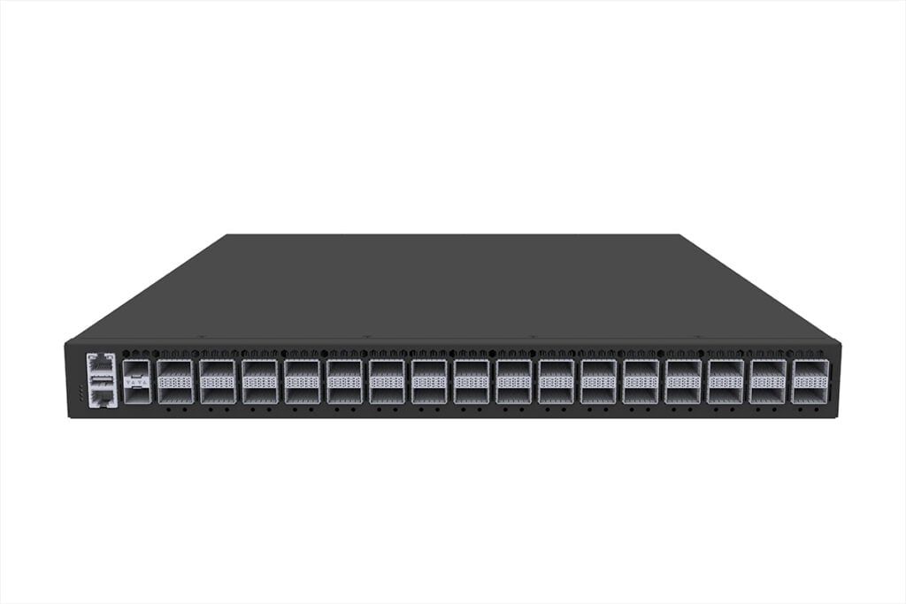
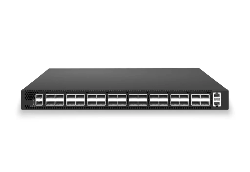
Related Data Center Switches: