Table of Contents
1. What Is Data Center Interconnect (DCI)?
Data Center Interconnect (DCI) refers to the networking technologies and infrastructure used to connect two or more geographically distributed data centers, enabling communication and resource sharing across compute, storage, applications, data, and network services. With the growth of cloud computing, AI infrastructure, and distributed applications, enterprises are increasingly adopting multi-data-center architectures to support business expansion, disaster recovery, resource allocation, data replication, and cross-region service deployment. As a result, DCI is no longer simply about connecting two data centers. It requires a comprehensive approach that considers bandwidth, latency, reliability, routing policies, optical transport capabilities, and security.
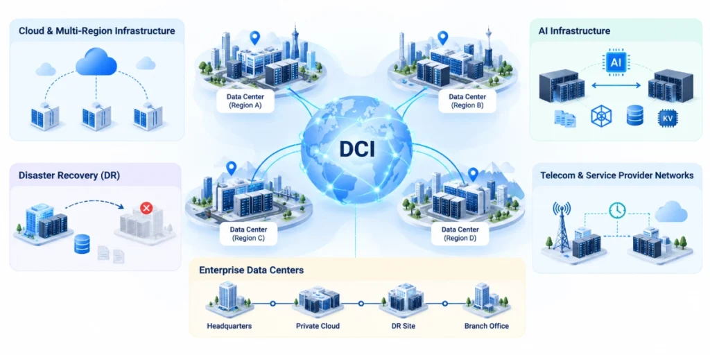
Typical DCI use cases include:
- Cloud & Multi-Region Infrastructure: Connecting cloud data centers across different regions to enable resource coordination and service deployment.
- Disaster Recovery (DR): Replicating data across multiple sites and supporting business recovery in the event of a failure.
- AI Infrastructure: Transferring training data, models, checkpoints, and inference-related data such as KV Cache between data centers.
- Enterprise Data Centers: Connecting corporate headquarters, private clouds, disaster recovery sites, and branch data centers.
- Telecom & Service Provider Networks: Supporting cross-site service delivery, network service interconnection, and time synchronization.
2. DCI Switch vs. Border Leaf Switch: Key Differences and Deployment Architectures
DCI (Data Center Interconnect) switches and Border Leaf switches are closely related, but the two terms describe fundamentally different aspects of network design. Border Leaf defines a switch’s role within a data center fabric, while DCI switch refers to the functionality a device provides for interconnecting multiple data centers. Depending on the network architecture, a single physical switch can serve both roles.
2.1 What Is a Border Leaf Switch?
A Border Leaf is a network edge node within a data center fabric, typically connecting the internal leaf-spine network to external networks. These connections may include WAN routers, enterprise networks, security appliances, or other data centers. The Border Leaf’s responsibilities depend on the network architecture. In a straightforward Layer 3 design, it may provide routed connectivity to an external network. In an EVPN-VXLAN Multi-Site architecture, a Border Leaf or Border Gateway may also terminate VXLAN tunnels, exchange EVPN routes, and handle traffic between local and remote sites.
For more about Border Leaf: https://cloudswit.ch/blogs/what-is-a-border-leaf-switch-how-to-choose/
2.2 What Is a DCI Switch?
A Data Center Interconnect (DCI) switch is a network switch used to carry traffic between data centers. Depending on the deployment architecture, it may provide Layer 3 routing, BGP connectivity, EVPN-VXLAN services, or other functions required to connect data center networks across a WAN.
Unlike a Border Leaf, which describes a specific position and function within a data center fabric, DCI switch is a broader term rather than a universally standardized hardware role. It may refer to an existing Border Leaf performing DCI functions, a dedicated interconnection gateway, or a switch deployed specifically for inter-site connectivity.
DCI can be implemented using conventional IP/BGP routing, EVPN-VXLAN Multi-Site, SRv6, or other supported interconnection technologies. The required capabilities depend on the network architecture rather than a fixed set of protocols.
SRv6-Based Traffic Engineering (Optional)
For deployments that use an SRv6-enabled WAN or service provider backbone, DCI gateways may support SRv6 Best-Effort (BE) forwarding and SRv6 Policy.
SRv6 BE provides connectivity using underlying routing paths, while SRv6 Policy enables more explicit control over traffic paths through selected network segments. When combined with suitable path computation, topology information, and traffic engineering mechanisms, SRv6 Policy can help operators steer inter-data-center traffic according to network performance and service requirements.
However, SRv6 is not a mandatory requirement for DCI. Conventional IP/BGP and EVPN-VXLAN Multi-Site deployments can operate without it.
Further Reading: SRv6 DCI Deployment — Three Inter-Domain Connectivity Models
2.3 Comparasion of DCI Switch vs. Border Leaf Switch
| Dimension | Border Leaf Switch | DCI Switch |
| Conceptual Nature | Architectural Role | Use Case / Capability |
| Primary Responsibility | Manages ingress/egress traffic and terminates policies between the internal Fabric and all external network domains | Focuses on inter-site routing, Layer 2/Layer 3 extension, and traffic relay across disparate data center sites |
| Connected Entities | Connects downstream to internal Spines; upstream to WAN routers, FW/LB appliances, security zones, or peer DCs | Connects locally to the data center Fabric (Border Leaf/Spine); upstream directly to long-haul inter-site transport links |
| Topological Location | Fixed at the edge of the data center Fabric (Leaf layer) | Can be the Border Leaf at the Fabric edge (integrated mode), or situated in a standalone WAN/DCI interconnect layer (decoupled mode) |
| Functional Scope | All-purpose egress: Handles inter-DC traffic, external Internet access, legacy VLAN integration, service chaining redirection, etc. | Dedicated interconnect: Tailored for inter-site workloads; focuses on cross-site route propagation, multi-tenant isolation, and long-haul encapsulation |
| SRv6 Requirements & Positioning | Non-essential (only required in integrated gateway designs): • Typically terminates EVPN-VXLAN internally and hands off pure IP / VRF-Lite externally without SRv6 awareness; • Only requires VXLAN-to-SRv6 cross-domain tunnel stitching and SID push/encapsulation when acting as a collapsed DCI Gateway facing the backbone directly | Core / high-demand requirement (depending on transport backbone): • Requires SRv6 Policy / SRv6 BE support across complex WAN/carrier backbones for latency/bandwidth-driven end-to-end TE and network slicing; • Runs EVPN over SRv6 to map intra-cloud traffic into wide-area SRv6 tunnels |
| Protocol & Hardware Requirements | Typically centers on intra-DC standard protocols (EVPN-VXLAN, VRF-Lite); hardware primarily uses standard high-throughput, low-latency switching silicon (shallow buffers) | Depends on interconnect model. Long-haul WAN scenarios often require SRv6/MPLS, EVPN Multi-Site tunnel stitching, split-horizon loop prevention, deep buffers, or coherent optics (ZR/ZR+) |
| Relationship Between the Two | Can be the same physical device (integrated mode), or two discrete devices connected in series (hierarchical decoupled mode) | |
2.4 DCI Switch vs. Border Leaf Switch: Three Deployment Models in Network Architecture
Based on design guides from leading networking vendors, the roles and boundaries of DCI switches and Border Leaf switches vary across different network architectures. These differences can be illustrated through three common deployment models.
2.4.1. Architecture A: Integrated Deployment (Border Leaf as DCI)
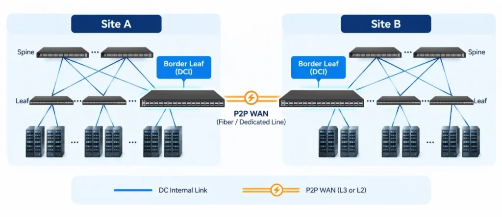
In this model, the Border Leaf switches at two sites are directly connected through fiber links or dedicated circuits, using either Layer 3 point-to-point connectivity or Layer 2 connectivity over short metropolitan distances. The Border Leaf switches directly handle DCI functions, eliminating the need for dedicated DCI switches. This approach offers a simplified, flat network architecture with minimal deployment costs. It is particularly suitable for metro-area active-active data centers and small- to medium-scale interconnections.
2.4.2. Architecture B:Dedicated DCI Switches Outside the Fabric
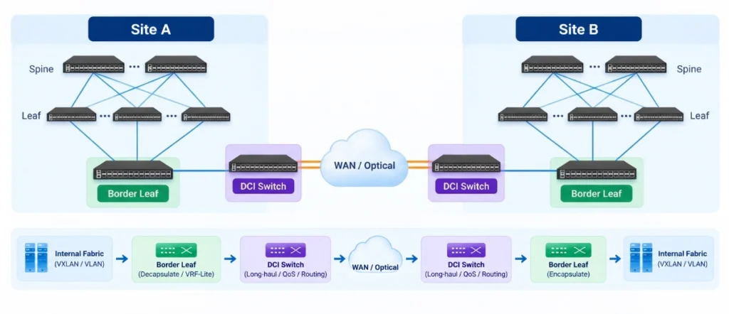
Both NVIDIA’s DCI design guide and Cisco’s AI inference routing white paper support this deployment model.
In this architecture, the Border Leaf switches are responsible only for decapsulating internal VXLAN or tenant traffic and forwarding it as native IP or through VRF-Lite connections to external DCI/ASBR devices.
The dedicated DCI switches then handle long-distance transport, routing across service provider backbone networks, and private WAN policies. The key advantage is complete separation of management domains and physical network infrastructure. By decoupling internal Fabric operations from the wide-area transport network, organizations can independently upgrade and expand their DCI capabilities without disrupting the existing Fabric. This also makes it easier to introduce optical transport systems, specialized QoS policies, or deep-buffering capabilities as needed.
2.4.3. Architecture C: Integrated EVPN Multi-Site Gateway
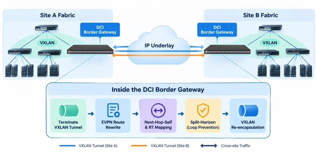
In this model, the switch goes beyond conventional routing and acts as a Border Gateway.
It terminates the site’s internal VXLAN tunnels, performs EVPN route modifications for inter-site traffic—including Next-Hop-Self and Route Target remapping—and re-encapsulates traffic into VXLAN for transport between sites. It also implements Split-Horizon mechanisms to prevent inter-site forwarding loops. The defining characteristic is the deep integration of advanced DCI protocol capabilities directly into Border Leaf hardware. Physically, the device remains a Border Leaf switch. However, at the protocol and control-plane levels, it provides the full functionality of a dedicated DCI gateway, eliminating the need for a separate gateway device.
3. Optical Transport Options for DCI: Carrier Services, DWDM and IPoDWDM
3.1 How Are Data Centers Connected Across Long Distances?
A DCI switch provides the network interface and routing functions needed to connect one data center to another. But when two data centers are separated by tens, hundreds, or even thousands of kilometers, what actually carries the traffic between them? The answer lies in the Wide Area Network (WAN) and the underlying optical transport infrastructure.
A typical DCI connection consists of three major components: a DCI switch or Border Leaf at each data center, a transport network between the sites, and the optical interfaces or services that connect them.
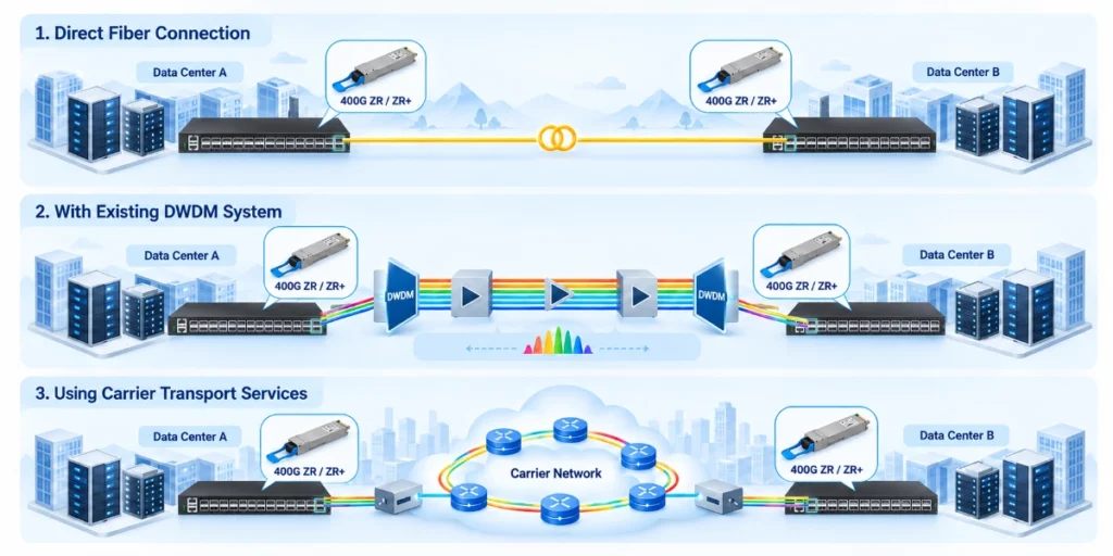
In practice, data centers can be interconnected through three common approaches, depending on transmission distance, bandwidth requirements, and available fiber infrastructure:
- Carrier-Provided WAN Connectivity
- Dedicated DWDM Optical Transport
- IP over DWDM (IPoDWDM)
| Connectivity Option | Typical Characteristics | Key Considerations |
|---|---|---|
| Carrier-Provided Dedicated Circuits or Ethernet Services | Inter-site connectivity provided by a service provider | Service-level agreements (SLAs), bandwidth, latency, and cost |
| Dedicated DWDM/ROADM Systems | Multiple wavelengths carried over optical transport equipment | Optical layer planning, scalability, and operational complexity |
| IP over DWDM (IPoDWDM) | Direct access to the DWDM optical layer using routers or switches equipped with compatible coherent optical transceivers | Transceiver compatibility, link budget, and optical layer conditions |
These options are not mutually exclusive. For example, IPoDWDM can operate over dedicated fiber, existing DWDM infrastructure, or compatible carrier-provided optical services.
3.1 How ZR/ZR+ Coherent Optics Enable IPoDWDM
Traditionally, connecting data centers over long distances required separate optical transport equipment between the DCI switches and the fiber network. While effective, this approach adds hardware, power consumption, and operational complexity.
ZR/ZR+ coherent optics are changing this.
With IP over DWDM (IPoDWDM), compatible ZR/ZR+ optical modules can be plugged directly into DCI switches or routers, allowing them to transmit high-speed Ethernet traffic over suitable long-distance fiber links or DWDM networks without separate transponders in certain deployments.
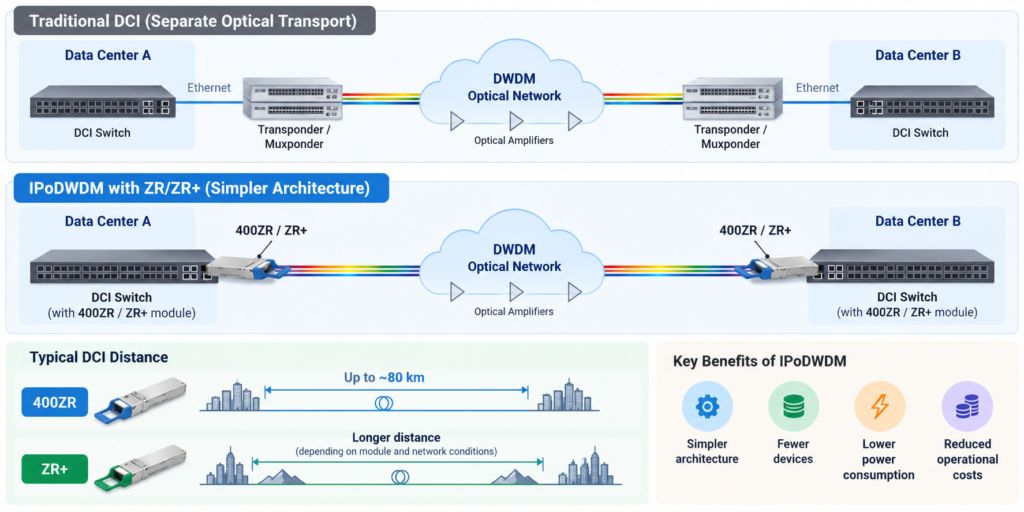
For example, 400G-ZR is designed primarily for high-capacity DCI connections over shorter optical spans, typically around 80 km, while ZR+ offers enhanced optical performance for longer-distance connections, depending on the module and network conditions. This more integrated approach can simplify network architecture, reduce equipment requirements, and potentially lower power and operating costs.

Why is IPoDWDM gaining momentum?
As cloud infrastructure and AI data centers continue to expand, operators need faster, more scalable connections between geographically distributed facilities. Instead of relying on separate packet and optical transport equipment for every connection, more organizations are adopting coherent pluggable optics directly in switches and routers.
Industry research reflects this shift. According to Dell’Oro Group, the IPoDWDM market is forecast to grow at a 27% compound annual growth rate through 2030, driven in part by increasing demand for ZR/ZR+ optics in data center interconnection.
IPoDWDM is becoming an increasingly important choice for high-capacity DCI, particularly in cloud and AI infrastructure, although traditional optical transport systems remain valuable for complex and ultra-long-haul networks. Actual deployment feasibility depends on transmission distance, fiber quality, optical link budget, module compatibility, and the capabilities of the optical line system.
4. Key DCI Use Cases
4.1 Multi-Availability Zone and Multi-Region Cloud Infrastructure
Cloud service providers and large enterprises typically deploy compute, storage, and application resources across multiple data centers to improve service availability and support geographic expansion. DCI can carry cross-site data replication, service access, management traffic, and resource scheduling traffic.
4.2 Disaster Recovery and Cross-Site Data Replication
Disaster Recovery (DR) is one of the key applications of DCI.
Data may need to be continuously replicated between a primary data center and a disaster recovery site, including databases, virtual machines, file systems, object storage, and application data. Network design should consider:
- Bandwidth allocation between regular business traffic and replication traffic.
- Congestion control during replication traffic bursts.
- Routing convergence and traffic recovery after failover.
- Encryption, access control, and tenant isolation.
- Recovery Point Objective (RPO) and Recovery Time Objective (RTO).
4.3 AI Data Center Interconnect
The growth of AI infrastructure is expanding the scope of DCI applications. Cross-data-center AI traffic may include:
- Training Data Transfer: Transferring datasets from storage platforms to compute clusters.
- Model and Checkpoint Synchronization: Distributing models, weights, and training checkpoints across different sites.
- Distributed Training: Coordinating GPU computation and communication across multiple data centers.
- Distributed Inference: Scheduling inference tasks across different compute resources or sites, and transferring model state or KV Cache as required by the architecture.
These traffic types do not have identical network requirements. For example, model and checkpoint transfers typically prioritize throughput, transfer efficiency, and recovery capabilities. Synchronous training across geographically distributed sites may be highly sensitive to round-trip time (RTT), jitter, and communication overhead. Distributed inference requires evaluating the deployment locations of Prefill and Decode, KV Cache data volumes, and service latency targets.
4.4 Telecom, Specialized Networks, and High-Precision Time Synchronization
Some telecommunications networks, media production systems, and other specialized applications require precise time synchronization across devices or sites. These networks may use IEEE 1588 Precision Time Protocol (PTP), Synchronous Ethernet (SyncE), or Global Navigation Satellite System (GNSS) time sources. Each technology serves a different purpose:
- PTP: Synchronizes device clocks using timestamps and clock synchronization protocols.
- SyncE: Distributes frequency synchronization through the Ethernet physical layer.
- GNSS: Provides an external time or frequency reference to devices equipped with the appropriate receiver and clock hardware.
Actual synchronization accuracy depends on the clock source, device clock performance, link asymmetry, network topology, calibration methods, and environmental conditions. Support for PTP or SyncE alone does not guarantee a specific level of end-to-end time accuracy.
5. Asterfusion DCI Switch Solutions: From IPoDWDM to Advanced Multi-Site Networking
Asterfusion offers flexible, high-performance Data Center Interconnect (DCI) switching platforms that support IPoDWDM connectivity with 400G/800G ZR/ZR+ coherent optical modules, multi-site EVPN-VXLAN interconnects, SRv6-based networking, and high-precision time synchronization.
By combining high-bandwidth switching, coherent optical transmission, and advanced networking capabilities, Asterfusion helps enterprises and service providers simplify DCI architectures, reduce deployment costs, and build efficient, scalable interconnect networks. Customers can select the most suitable DCI switching platform based on their port capacity requirements, coherent optics compatibility, and specific networking needs.
5.1 High-Bandwidth DCI with ZR/ZR+ Coherent Optics
For data centers requiring high-capacity optical connectivity, Asterfusion switches support compatible ZR/ZR+ coherent transceivers across a range of Ethernet platforms. These solutions can integrate with suitable fiber and DWDM infrastructure, reducing the need for separate optical transport equipment in certain deployments.
| Model | Port Configuration | Max. ZR/ZR+ Modules |
| CX864E-N | 64 × 800G | 32 |
| CX764QD-N / CX764QO-N | 64 × 400G | 32 |
| CX732Q-M-H / CX732Q-N | 32 × 400G | Up to 12* (Below 30°C) |
| CX664D-N | 64 × 200G | 16 |
| CX564P-N | 64 × 100G | 16 |
| CX532P-M-H / CX532P-N | 32 × 100G | 8 |
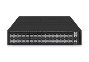
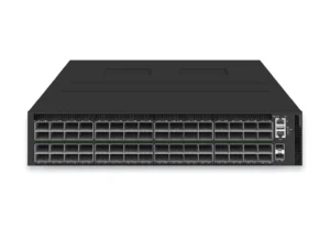


The maximum ZR/ZR+ module counts listed above are based on an operating temperature range of 0–35°C and validated configurations. For CX732Q models, the standard configuration supports 8 modules. At inlet temperatures below 30°C, higher-density configurations with approximately 12–16 modules may be possible, depending on the power consumption and thermal characteristics of the specific ZR/ZR+ transceivers. Please contact the Asterfusion team to confirm the maximum supported module count for your hardware configuration and deployment conditions.
5.2 Advanced DCI Gateway: EVPN-VXLAN Multi-Site, SRv6 and Precision Timing
Beyond optical connectivity, Asterfusion supports three additional DCI requirements:
- EVPN-VXLAN Multi-Site: Connects independent data center fabrics while preserving site-level network boundaries.
- SRv6: Enables IPv6 Segment Routing-based connectivity across data center and backbone networks.
- PTP Precision Timing: Provides accurate time synchronization for timing-sensitive applications, with SyncE and GNSS available on supported platforms.
| Model | Port Configuration | EVPN-VXLAN Multi-Site | SRv6 | PTP/SynE | ZR/ZR+ |
| CX732Q-M-H | 32 × 400G | Yes | Yes | Class C -capable | Yes |
| CX532P-M-H | 32 × 100G | Yes | Yes | Class C-capable | Yes |
| CX764QH-N | 64 × 400G | Yes | Yes | Not confirmed | NO |
| CX308P-48Y-M-H | 48 × 25G + 8 × 100G | Yes | Yes | Optional Class C | NO |
| CX306P-48Y-M-H | 48 × 25G + 6 × 100G | Yes | Yes | PTP + optional GNSS | NO |
-
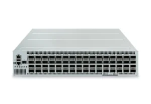 400G AI Ethernet Switch with 64x QSFP112 Ports, 25.6Tbps, Enterprise SONiC Ready
-
 48-Port 25G Switch with 6 Port 100G Uplink, Optional OCTEON DPUs
-
 32-Port 400G QSFP-DD Core/Spine Switch Enterprise SONiC Ready
-
 48-Port 25G 8-Port 100G Uplink Enterprise SONiC Ready
-
 32-Port 100G QSFP28 Core Switch Enterprise SONiC Ready
5.3 Featured DCI Switch: CX732Q-M-H — One Platform, Multiple DCI Capabilities
Powered by AsterNOS Enterprise SONiC and built on the Marvell Falcon ASIC, the Asterfusion CX732Q-M-H combines 32 × 400G high-speed ports with advanced networking capabilities in a single platform.
It supports ZR/ZR+ coherent optics for high-bandwidth optical interconnection, EVPN-VXLAN Multi-Site for connecting independent data center fabrics, SRv6 for IPv6-based inter-domain networking, and Class C-capable PTP for precision timing applications. With the flexibility of Enterprise SONiC and this combination of hardware and software capabilities, the CX732Q-M-H is well suited to cloud operators, enterprises, and service providers seeking a versatile DCI solution. From optical transport to advanced routing and precision timing, the CX732Q-M-H brings multiple DCI capabilities together on one Enterprise SONiC-powered platform.
6. How to Choose the Right Asterfusion DCI Switch
Choosing the right Data Center Interconnect (DCI) switch starts with understanding the network architecture and the specific requirements between data centers. Some deployments need straightforward Layer 3 connectivity through existing Border Leaf switches, while others require EVPN-VXLAN Multi-Site, high-capacity coherent optical transport, SRv6, or precision time synchronization.
6.1 Table maps five common DCI scenarios to suitable Asterfusion switching platforms.
| DCI Deployment Scenario | Recommended Asterfusion Models | Key Capabilities & Selection Criteria |
| 1. IP/BGP-Based DCI (Border Leaf) — Traditional Layer 3 connectivity between enterprise data centers, disaster recovery sites, and cloud networks | CX532P-N, CX564P-N, CX664D-N, CX732Q-N | Uses conventional IP routing and BGP for inter-site connectivity. This scenario substantially overlaps with the Border Leaf role: existing Border Leaf switches can provide DCI connectivity without a dedicated DCI Gateway, provided they meet routing, interface, and capacity requirements. |
| 2. EVPN-VXLAN Multi-Site DCI — Interconnecting independent EVPN-VXLAN fabrics across multiple data centers or cloud regions | CX732Q-M-H, CX532P-M-H, CX764QH-N, CX308P-48Y-M-H, CX306P-48Y-M-H | EVPN-VXLAN Multi-Site capabilities for connecting independent data center fabrics. Select based on required inter-fabric connectivity, routing functions, port capacity, and interoperability. A suitably equipped Border Leaf may also serve as a Multi-Site Gateway. |
| 3. High-Capacity IPoDWDM DCI — AI data center interconnection, cloud infrastructure, large-scale data replication, and high-bandwidth optical links | CX864E-N, CX764QD-N, CX764QO-N, CX732Q-N, CX732Q-M-H, CX664D-N, CX564P-N, CX532P-N | Compatible ZR/ZR+ coherent optics for integration with suitable fiber or DWDM infrastructure. Evaluate required inter-site bandwidth, optical reach, validated coherent module density, power consumption, and cooling conditions. |
| 4. SRv6-Enabled DCI — SRv6-based cloud backbones, inter-domain connectivity, and networks requiring specific SRv6 service functions | CX732Q-M-H, CX532P-M-H, CX764QH-N | SRv6 capabilities for deployments adopting IPv6 Segment Routing. Confirm the required SRv6 endpoint behaviors, service functions, software release, and interoperability. SRv6 is optional and is not a prerequisite for conventional IP/BGP, EVPN Multi-Site, or IPoDWDM DCI. |
| 5. Precision Timing DCI — Inter-data-center time synchronization, financial infrastructure, and timing-sensitive distributed applications | CX306P-48Y-M-H, CX308P-48Y-M-H, CX532P-M-H, CX732Q-M-H | Asterfusion’s 1G–800G switches support IEEE 1588v2 PTP, with synchronization capabilities for 5G O-RAN/xHaul (ITU-T G.8275.x), broadcast media (SMPTE ST 2059-2 / AES67), and general campus/data center networks (IEEE 1588v2), subject to model and software configuration. The CX306P-48Y-M-H additionally supports SyncE and GNSS and has been selected for a real-world customer project involving inter-data-center time synchronization. |
Product suitability depends on the AsterNOS Enterprise SONiC software release, hardware configuration, transceiver validation, and deployment conditions. Coherent optics density, SRv6 functions, EVPN Multi-Site features, and precision timing capabilities should be confirmed for the intended configuration.
6.2 Additional Hardware Considerations
Beyond the DCI architecture, packet buffering and routing scale may influence switch selection.
For burst-heavy traffic such as large-scale data replication and distributed storage, Asterfusion’s Marvell Teralynx 7 and Teralynx 10-based platforms offer packet buffer capacities of 70 MB and up to 200 MB, respectively. These buffers can help accommodate temporary traffic bursts, although congestion management and link capacity remain essential.
For large-scale Layer 3 interconnection, the Marvell Falcon-based CX532P-N-V2 (32 × 100G) and CX732Q-N-V2 (32 × 400G) offer hardware specifications of up to 288K IPv4 host/prefix entries, 144K IPv6 host/prefix entries, and 128K MAC entries, subject to shared resource allocation and software support.
Building a More Flexible DCI Network with Enterprise SONiC
There is no one-size-fits-all approach to Data Center Interconnect. Some networks require straightforward IP/BGP connectivity through existing Border Leaf switches, while others demand EVPN-VXLAN Multi-Site, high-capacity IPoDWDM, SRv6, or precise time synchronization.
The key is to choose a DCI architecture that meets today’s requirements while leaving room for future expansion—without introducing unnecessary complexity or vendor lock-in.
Powered by AsterNOS Enterprise SONiC, Asterfusion’s 1G–800G switching portfolio combines open networking software with flexible hardware options for diverse DCI deployments. From conventional Layer 3 interconnection to advanced multi-site networking, coherent optical connectivity, and precision timing, Asterfusion helps organizations build scalable, adaptable data center networks.
Planning a DCI deployment? Contact Asterfusion to explore the right switching platform for your network architecture, bandwidth requirements, and interconnection needs.


