Table of Contents
As cloud computing, AI infrastructure, and distributed applications continue to expand, enterprises and cloud providers increasingly need reliable, high-bandwidth connectivity between geographically distributed data centers. Beyond physical connectivity, DCI also requires efficient routing, network virtualization, traffic engineering, and fast failure recovery.
Enterprise SONiC provides an open and flexible foundation for scalable DCI networks. With Asterfusion Enterprise SONiC (AsterNOS), network operators can build architectures tailored to their needs using BGP Layer 3 routing, EVPN-VXLAN, SRv6, and high-speed optical connectivity. Asterfusion is also advancing its Integrated EVPN Multi-Site Gateway capabilities to support more complex cross-site EVPN deployments.
This article explores the following key topics:
- DCI Architecture: Two deployment models—Border Leaf and Dedicated DCI Switch—and their respective design considerations.
- BGP Layer 3 DCI: Using BGP, VRF, ECMP, and BFD to establish routed connectivity between independent data centers.
- EVPN-VXLAN Multi-Site Gateway: Cross-site EVPN route propagation, VXLAN decapsulation and re-encapsulation, Split-Horizon mechanisms, and AsterNOS features and roadmap.
- SRv6 Inter-Domain DCI: An in-depth analysis of three inter-domain deployment models: Option A (VRF Stitching), Option B (Relay SID Translation), and Option C (End-to-End SRv6).
- 400G/800G IPoDWDM: High-speed switching interfaces, ZR/ZR+ coherent optical transceivers, and data center optical interconnect architectures.
- Network Observability & Automation: Enabling cross-site network monitoring and automated operations through INT, Prometheus, Grafana, and open management interfaces.
- Asterfusion DCI Platforms: Selecting the right Enterprise SONiC switch platform based on port capacity, network protocols, optical transceiver compatibility, and deployment requirements.
1. What Is Data Center Interconnect (DCI)?
Data Center Interconnect (DCI) refers to a network architecture that connects two or more independent data centers through IP networks, Ethernet private lines, dedicated fiber-optic links, or DWDM optical transport infrastructure. Its primary goal is to establish reliable network connectivity between geographically distributed sites, enabling business systems to exchange data, access remote resources, and support cross-site application deployments.
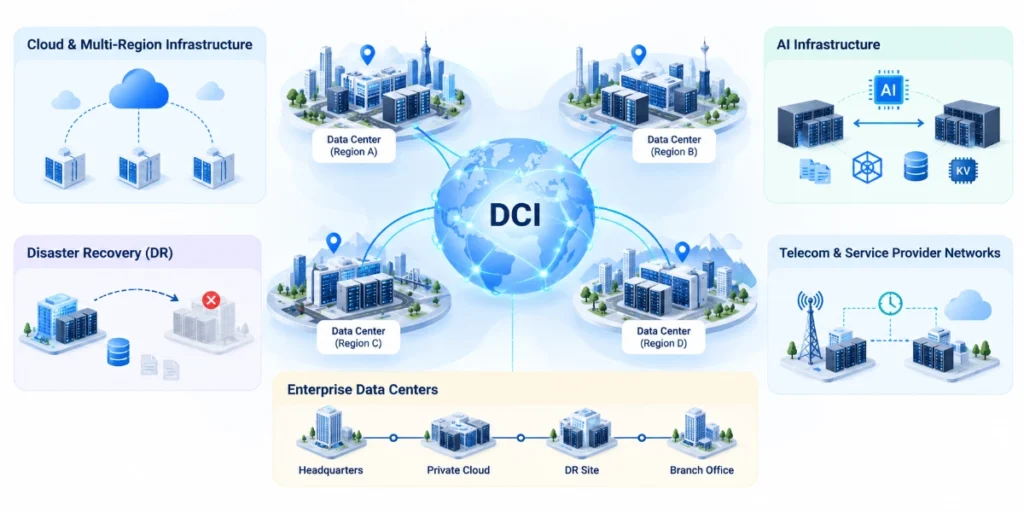
For more information:What Is Data Center Interconnect ? DCI Border Leaf Switches, IPoDWDM & SRv6 – Asterfusion Data Technologies
1.1 Key Design Challenges in Modern DCI
As the number of sites and bandwidth requirements continue to grow, DCI networks must address several key challenges:
- How can routing reachability be established between independent data centers?
- How can network isolation be maintained in multi-tenant environments?
- How can Overlay and Underlay connectivity be managed across different network domains?
- How can boundary gateways be prevented from becoming scalability bottlenecks?
- How can traffic paths be controlled across multiple network domains?
- How can redundancy and fast failure detection improve network availability?
- How can 400G/800G interfaces and coherent optical technologies simplify high-speed interconnects?
- How can real-time observability be achieved across distributed sites?
These challenges cannot be addressed by a single network protocol alone.
Modern DCI requires an integrated design approach that considers network architecture, the control plane, the data plane, and the optical transport layer as a unified system.
2. DCI Network Architectures: Border Leaf vs. Dedicated DCI Switch
DCI switches and Border Leafs are not entirely different device types. Rather, they represent different roles within a network architecture. A Border Leaf is an edge node within a data center Leaf-Spine Fabric responsible for external connectivity, while a DCI Switch is a network device dedicated to interconnecting multiple data centers. Depending on deployment scale and operational requirements, Enterprise SONiC-based DCI networks typically adopt one of two architectures.
2.1 Integrated Border Leaf DCI
In an integrated architecture, the Border Leaf performs both data center fabric boundary functions and inter-site connectivity. Border Leafs can use routing protocols such as BGP to exchange inter-site network reachability information and handle the corresponding overlay or service routing functions based on the selected network design. This architecture reduces the number of dedicated DCI devices and is suitable for deployments with relatively manageable network scales and clearly defined site boundaries.
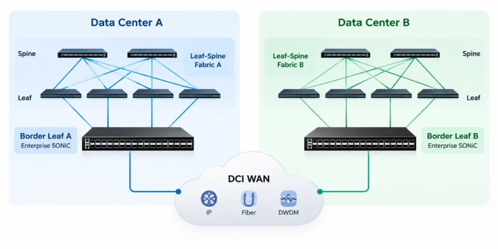
However, since Border Leafs handle both internal and external connectivity, careful consideration must be given to routing scale, interface capacity, redundancy, and fault domains.
2.2 Dedicated DCI Switch Architecture
For larger environments with more sites, or deployments where independent DCI network management is preferred, dedicated DCI switches can be deployed. Dedicated DCI switches separate inter-site connectivity from the internal data center fabric.
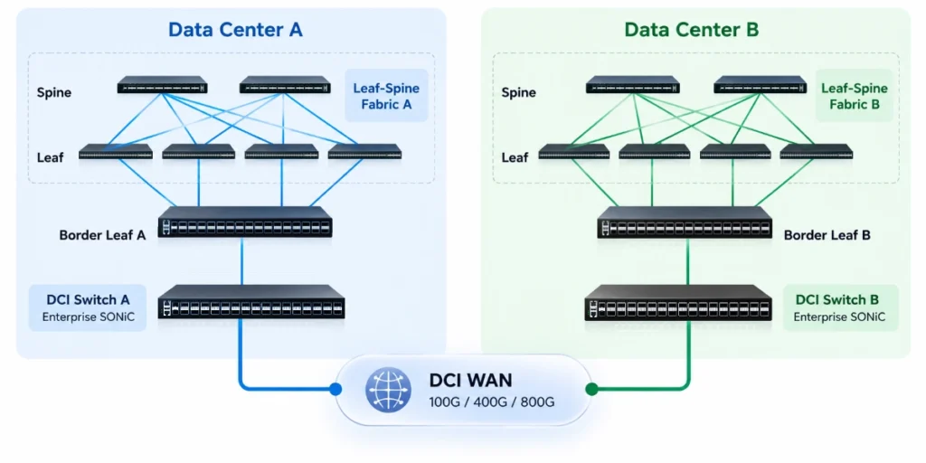
This architecture offers several advantages:
- Independent DCI resource planning: DCI bandwidth and port resources can be planned and allocated independently.
- Clear routing boundaries: Establishes a clear separation between internal data center routing and external connectivity.
- Centralized policy management: Enables centralized implementation of inter-site routing and service policies.
- Simplified operations: Reduces operational dependencies between the internal fabric and external transport network.
- Independent scalability: Allows DCI network capacity to be expanded independently as business requirements grow.
Both architectures can be implemented using Enterprise SONiC. The key selection criterion is not the device name, but rather the control-plane and data-plane functions required for inter-site connectivity.
3. BGP EVPN-VXLAN for Multi-Site DCI: Architecture, Gateway Functions, and Roadmap
In multi-site Data Center Interconnect (DCI) environments, networks must provide more than IP reachability between different sites. They must also support tenant isolation, virtual network connectivity, and cross-site traffic forwarding to meet specific business requirements.
Enterprise SONiC-based DCI networks can adopt two primary approaches: using BGP to establish Layer 3 routed connectivity between independent data centers, or leveraging BGP EVPN-VXLAN to interconnect virtualized networks. For data centers that have deployed EVPN-VXLAN fabrics, EVPN-VXLAN Multi-Site DCI provides an architecture for interconnecting independent data center fabrics while maintaining site-level network boundaries. Multi-Site Border Gateways (BGWs) play a key role in handling inter-site EVPN route exchange and VXLAN traffic forwarding.
Asterfusion provides EVPN-VXLAN capabilities across selected CX-N and CX-M-H platforms, supporting different levels of Multi-Site DCI functionality. While these platforms offer foundational EVPN-VXLAN features, the availability of advanced Multi-Site Gateway functions varies by hardware platform. The complete Integrated EVPN Multi-Site Gateway solution is still under development on selected CX-N platforms and is not currently supported on CX-M-H platforms. Feature availability depends on the specific hardware model and AsterNOS software release.
3.1 BGP Routing for Layer 3 DCI
For scenarios that do not require Layer 2 network extension across sites, BGP-based Layer 3 DCI offers a straightforward, scalable, and easy-to-manage network architecture. In this design, each data center can operate its own independent Leaf-Spine fabric, maintaining separate IP addressing schemes and routing domains. Border Leafs or DCI switches establish routed connectivity with remote data centers and exchange designated service network prefixes. For example, two data centers can be deployed in different Autonomous Systems (ASes), establishing inter-site routing adjacency through eBGP.
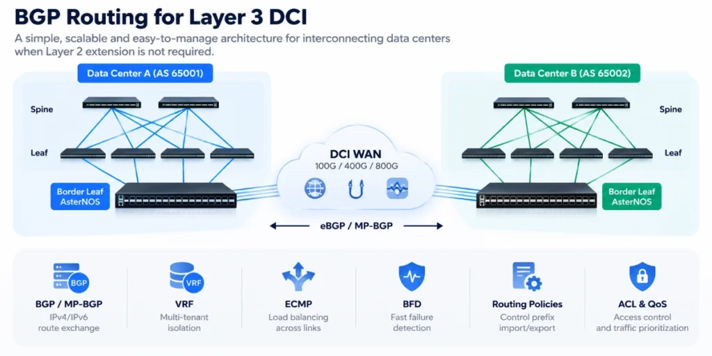
Key AsterNOS Enterprise SONiC capabilities include:
- BGP / MP-BGP: Supports the exchange of IPv4/IPv6 network reachability information and routes across relevant address families.
- VRF (Virtual Routing and Forwarding): Maintains separate routing tables for different tenants and services, providing Layer 3 network isolation.
- ECMP (Equal-Cost Multi-Path): Distributes traffic across multiple equal-cost paths to improve link utilization.
- BFD (Bidirectional Forwarding Detection): Enables fast detection of supported link or routing-neighbor failures, helping accelerate routing convergence.
- Routing Policies: Controls prefix advertisement, route import and export, and path selection through routing policies.
- ACL and QoS: Provides access control, traffic classification, and priority management for inter-site services.
When multiple interconnection links exist between data centers, ECMP, BFD, and redundant Border Leaf designs can be combined to improve network reliability. A major advantage of Layer 3 DCI is that it eliminates the need to extend the same Layer 2 broadcast domain across different data centers, simplifying fault-domain management. Therefore, BGP Layer 3 DCI is often a solution worth prioritizing for inter-site application access, data replication, disaster recovery, and connectivity between independent cloud networks.
3.2 EVPN-VXLAN for Multi-Site Data Center Connectivity
Within a single data center, EVPN-VXLAN can connect virtual networks across different Leaf switches.It is important to distinguish basic EVPN-VXLAN connectivity from a complete EVPN-VXLAN Multi-Site DCI architecture. While BGP EVPN, VXLAN, and VTEP capabilities provide the foundation for overlay networking, a full Multi-Site deployment requires additional inter-site gateway functions to manage EVPN route propagation, VXLAN traffic forwarding, and site-level traffic isolation. When the network expands across multiple data centers, operators must also consider how to exchange EVPN routes between sites, handle VXLAN traffic, and prevent Layer 2 broadcast domains and failure domains from expanding without proper control. A common design approach is to establish a dedicated inter-site boundary at each data center. Depending on the architecture, this boundary may be implemented using Border Leaf switches or dedicated Multi-Site Border Gateways (BGWs).
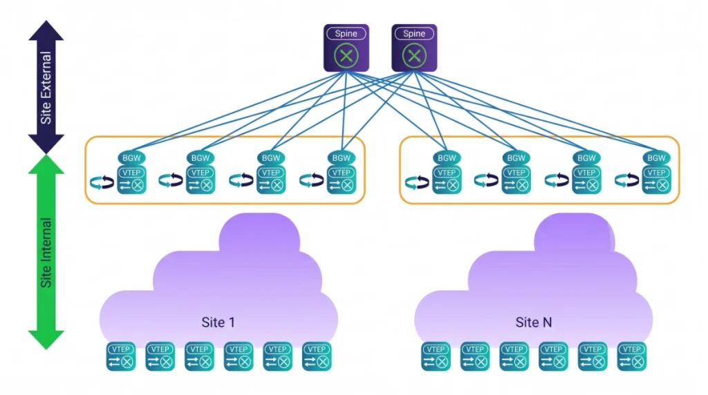
In a full EVPN-VXLAN Multi-Site architecture, BGWs provide the specific gateway functions required for cross-site connectivity, including EVPN route exchange, VXLAN traffic processing, and Split-Horizon mechanisms for inter-site traffic isolation.The availability of these gateway functions depends on the implementation and hardware platform. Supporting basic EVPN-VXLAN features does not necessarily mean that a switch supports the complete Multi-Site BGW functionality. This allows each data center to maintain a relatively independent network topology while establishing controlled cross-site overlay connectivity according to business requirements.
Key EVPN-VXLAN Technical Components
VTEP (VXLAN Tunnel Endpoint)
A VTEP handles VXLAN encapsulation and decapsulation. Within a data center fabric, Leaf switches typically act as VTEPs, encapsulating traffic from local servers and forwarding it through the IP Underlay network to remote VTEPs.
L2VNI (Layer 2 VXLAN Network Identifier)
An L2VNI identifies a Layer 2 virtual network, allowing different VLANs or tenant networks to maintain logical isolation over shared physical infrastructure.
L3VNI (Layer 3 VXLAN Network Identifier)
An L3VNI works with VRFs to provide Layer 3 network virtualization for different tenants and support inter-subnet routing.
BGP EVPN Route Types
AsterNOS supports EVPN Route Types 2, 3, and 5:
- Type 2 — MAC/IP Advertisement Route: Advertises endpoint MAC addresses and their associated IP reachability information.
- Type 3 — Inclusive Multicast Ethernet Tag Route: Provides the information required to establish forwarding for Broadcast, Unknown Unicast, and Multicast (BUM) traffic.
- Type 5 — IP Prefix Route: Advertises IP prefixes, providing the control-plane foundation for Layer 3 connectivity over EVPN.
3.3 Integrated EVPN Multi-Site Gateway Architecture
In an Integrated EVPN Multi-Site Gateway architecture, a Border Leaf configured as a Multi-Site Border Gateway (BGW) not only connects the local fabric to the inter-site network but also performs cross-site EVPN route processing and VXLAN traffic forwarding. Compared with simply connecting the VXLAN networks of two data centers directly, this architecture establishes clearly defined site boundaries, helping operators control EVPN route propagation, overlay forwarding paths, and traffic exchange between different sites.
A complete Integrated EVPN Multi-Site Gateway architecture typically involves multiple control-plane and data-plane functions working together.
EVPN Route Re-advertisement
EVPN Route Re-advertisement handles EVPN route propagation between different sites.
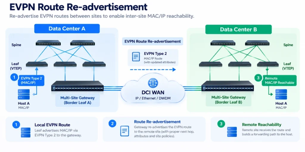
In a multi-site network, MAC/IP reachability information learned by a local fabric may need to be processed by the Multi-Site Gateway before being advertised to remote sites. For example, a Leaf switch in Data Center A advertises a server’s MAC/IP information through an EVPN Type 2 route. Based on inter-site routing policies, the Multi-Site Gateway can advertise the relevant reachability information to Data Center B, allowing the remote network to establish a forwarding path to that endpoint. In architectures that use route re-advertisement, the gateway must also handle EVPN Next Hop information, route attributes, and site-boundary information according to the network design. This capability is an important component of the control plane in Integrated EVPN Multi-Site Gateway architectures.
VXLAN Decapsulation
VXLAN Decapsulation refers to the process in which a gateway receives a VXLAN-encapsulated packet, removes the corresponding outer encapsulation, and recovers the inner service packet for subsequent forwarding or processing. For example, a Leaf switch in Data Center A encapsulates server traffic into VXLAN packets and forwards them to the local Multi-Site Gateway. After receiving the packets, the gateway performs the corresponding decapsulation and forwarding operations based on the VNI, forwarding tables, and destination network information.
This process enables the gateway to handle traffic between different overlay forwarding domains or forwarding paths.
VXLAN Re-encapsulation
When inter-site traffic needs to be forwarded through a new VXLAN tunnel, the Multi-Site Gateway can re-encapsulate the data packets.
A typical cross-site forwarding process may involve the following steps:
- The local Leaf encapsulates the service packet into VXLAN traffic.
- The local Multi-Site Gateway receives and processes the VXLAN packet.
- Based on remote-site reachability information and forwarding policies, the gateway determines the next VXLAN tunnel.
- The gateway encapsulates the traffic using the appropriate outer IP addresses and VXLAN parameters, then forwards it to the remote gateway.
- The remote gateway delivers the traffic to the remote fabric based on the destination VNI and forwarding information.
Through decapsulation and re-encapsulation, the gateway can establish connectivity between different VXLAN forwarding segments. It is important to note that the specific data-plane processing depends on the Multi-Site Gateway architecture being deployed. Not all cross-site VXLAN solutions require two separate VXLAN encapsulation stages.
Anycast Border Gateway (A-BGW)
For high-availability EVPN-VXLAN Multi-Site deployments, multiple Border Gateways can be deployed within the same data center site using an Anycast Border Gateway architecture. These gateways can share an Anycast address, providing redundant inter-site connectivity and enabling traffic distribution across multiple gateway devices, depending on the network design and forwarding mechanisms.
It is important to distinguish an Anycast Border Gateway from an Anycast Gateway. An Anycast Gateway provides a distributed default gateway for endpoints across Leaf switches, while an Anycast Border Gateway provides redundant connectivity at the data center fabric boundary.
Split-Horizon
Split-Horizon is an important mechanism in EVPN-VXLAN Multi-Site deployments for preventing unnecessary traffic reflection and forwarding loops. In a Multi-Site architecture, the gateway must distinguish between traffic originating from the local fabric and traffic received from other sites, applying forwarding rules to prevent inappropriate or duplicate forwarding.
For example, BUM traffic received from a remote site should not be forwarded back across other inter-site connections without appropriate controls, as this could result in duplicate traffic or potential forwarding loops. By restricting forwarding in specific directions, Split-Horizon helps maintain the stability of the cross-site overlay network. This mechanism is particularly important for controlling Broadcast, Unknown Unicast, and Multicast (BUM) traffic across multiple sites.
Route Target Remapping
Route Target (RT) controls how EVPN routes are imported into and exported from different VRFs or EVPN instances. In some multi-site deployments, different data centers may use different Route Target configurations.
When connectivity between these independent routing domains is required, Route Target Remapping or related routing policy mechanisms can be used to translate or modify the RT attributes of inter-domain EVPN routes. This helps enable controlled route exchange while preserving the independence of local network policies. However, RT Remapping is not a mandatory requirement for every EVPN Multi-Site architecture. If different sites use compatible RT configurations, additional RT translation may not be necessary.
Please note: not all of these capabilities are currently available across every Asterfusion hardware platform. Some functions are supported, while others remain under development or are not currently supported on specific platforms. The following section provides a detailed overview of feature availability across the CX-N and CX-M-H product families.
3.4 AsterNOS EVPN-VXLAN Multi-Site Capabilities and Development Roadmap
Asterfusion Enterprise SONiC already provides the foundational capabilities required to build EVPN-VXLAN networks, including BGP EVPN Type 2/3/5 routes, VTEP, L2VNI/L3VNI, VRF, and VXLAN forwarding. However, the availability of advanced EVPN-VXLAN Multi-Site functions varies by hardware platform. While both CX-N and CX-M-H platforms support several underlying EVPN-VXLAN capabilities, their support for advanced Multi-Site Gateway functions differs.
Based on current R&D feedback, the status of the relevant capabilities is summarized below:
| Feature | CX-N Platforms | CX-M-H Platforms |
|---|---|---|
| BGP EVPN Type 2/3/5 | Supported | Supported |
| VXLAN Decapsulation | Supported | Supported |
| VXLAN Re-encapsulation | Supported | Supported |
| Split-Horizon | Supported | Not currently supported |
| EVPN Route Re-advertisement | Further development on the roadmap | Not currently supported |
| Route Target Remapping | On roadmap | Not currently supported |
| Complete Integrated EVPN Multi-Site Gateway | On roadmap for selected platforms | Not currently supported |
The development of these advanced capabilities will further expand the applicability of AsterNOS in complex EVPN-VXLAN DCI environments.
For customers considering Multi-Site Gateway deployments, Asterfusion can assess the currently available capabilities of the target hardware platform and identify additional development requirements based on the actual site topology, EVPN control-plane design, VXLAN forwarding requirements, and hardware selection.
This approach allows customers to plan their network evolution on an open Enterprise SONiC architecture, with a clear understanding of current platform capabilities and the potential development roadmap.
3.5 EVPN-VXLAN vs. SRv6 for DCI
Both EVPN-VXLAN and SRv6 can be used for Data Center Interconnect (DCI), but they differ significantly in their underlying mechanisms and architectural focus.
EVPN-VXLAN primarily uses the BGP EVPN control plane and VXLAN data encapsulation to provide virtualized network connectivity, MAC/IP reachability distribution, and multi-tenant overlay networking. For environments that require Layer 2 network extension, VNI-based isolation, or connectivity with existing VXLAN fabrics, EVPN-VXLAN is an important technology choice.
SRv6, on the other hand, uses IPv6 Segment Routing and Segment Identifiers (SIDs) to provide IPv6-based service forwarding, inter-domain connectivity, and path control capabilities.
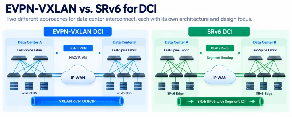
For networks that require interconnection across Autonomous Systems, programmable forwarding, or policy-based path control, SRv6 offers an alternative architectural approach.
| Comparison | EVPN-VXLAN | SRv6 |
|---|---|---|
| Primary Data Plane | VXLAN over UDP/IP | IPv6 / SRv6 |
| Key Identifiers | VNI, MAC/IP routes | Locator, SID |
| Control Plane | BGP EVPN | BGP, IS-IS, etc., depending on the architecture |
| Primary Applications | Overlay virtualization, multi-tenant connectivity, Layer 2 and Layer 3 service interconnection | IPv6 programmable forwarding, inter-domain service connectivity, traffic engineering |
| Key Cross-Site Design Considerations | EVPN route propagation, VTEP, Gateway, BUM traffic control | SID reachability, inter-domain routing, Endpoint Behaviors |
| Path Control | Based on IP Underlay and associated routing policies | Can leverage SRv6 Policy and Segment Lists |
| Typical Architectures | EVPN-VXLAN DCI / Multi-Site Gateway | SRv6 Option A / B / C |
It is important to emphasize that EVPN-VXLAN and SRv6 are not simply competing or interchangeable technologies.
In some network designs, EVPN-VXLAN can continue to operate within individual data centers, while the inter-site network uses an independent Layer 3 routing or SRv6 transport architecture. The two technologies can work together through appropriate boundary nodes, routing policies, and service interconnection mechanisms. Therefore, technology selection should not depend solely on the protocols themselves, but should also consider the following factors:
- Is Layer 2 network extension across sites required?
- Has an EVPN-VXLAN fabric already been deployed?
- Is connectivity across different Autonomous Systems required?
- Is IPv6-based programmable forwarding needed?
- Is explicit service path control required?
- How many tenant and service states must boundary devices maintain?
- Which forwarding behaviors are supported by the switching ASIC and network operating system?
For networks looking to further simplify inter-domain service forwarding, control ASBR state scale, or achieve end-to-end IPv6 connectivity, SRv6 offers an architectural approach worth evaluating in greater detail.
The next section introduces three inter-domain deployment models for Asterfusion SRv6 DCI: Option A (VRF Stitching), Option B (Relay SID and SID Translation), and Option C (End-to-End Seamless SRv6), examining their respective control-plane mechanisms, data-plane operations, and applicable scenarios.
4. SRv6-Based DCI: Three Inter-Domain Connectivity Architectures and Their Forwarding Mechanisms
SRv6 (Segment Routing over IPv6) combines Segment Routing with the IPv6 data plane, using Segment Identifiers (SIDs) to represent specific network forwarding behaviors.
In multi-site DCI environments, SRv6 can be used not only for traffic path control but also to handle service route propagation, SID translation, and packet forwarding between Autonomous Systems through different inter-domain deployment models. Asterfusion’s SRv6 DCI solution focuses on three deployment models:
- Option A: Hierarchical VRF Stitching and Service Termination
- Option B: Relay Lookup and SID Translation
- Option C: End-to-End Seamless SRv6
The key differences among these three models lie in whether inter-domain boundary devices maintain tenant service state, whether SIDs need to be modified, and whether end-to-end Locator reachability is required.
Further Reading: SRv6 DCI Deployment: Three Inter-Domain Deployment Modes Explained
4.1 Key SRv6 Technical Components
Before examining the three deployment models, it is important to understand several key concepts.
SRv6 Locator
Identifies an SRv6 node or the IPv6 address space associated with its SIDs. The Underlay network must provide reachability to the relevant Locators according to the architecture design.
Segment Identifier (SID)
An IPv6 address that represents a forwarding instruction or service behavior.
Endpoint Behavior
Defines how a node processes a packet when it matches a specific SID.
Relevant SRv6 capabilities in AsterNOS include End, End.X, End.DT4, End.DT6, and End.DT46 behaviors.
These include:
- End: Basic SRv6 endpoint processing.
- End.X: A forwarding behavior associated with a specific Layer 3 adjacency.
- End.DT4: Decapsulates the packet and performs a lookup in a designated IPv4 routing table.
- End.DT6: Decapsulates the packet and performs a lookup in a designated IPv6 routing table.
- End.DT46: Decapsulates the packet and performs a lookup in a designated dual-stack routing table.
ASBR (Autonomous System Boundary Router)
A boundary router that connects different Autonomous Systems.
PE (Provider Edge)
An edge node responsible for service access, VPN routing, and the corresponding SRv6 service encapsulation or termination functions.
4.2 Option A: VRF Stitching and Segmented Service Termination
Option A adopts a segmented inter-domain connectivity model.
ASBRs in different Autonomous Systems exchange IPv4/IPv6 unicast routes through standard eBGP and maintain the corresponding tenant VRFs at the inter-domain boundary.
Typical architecture:
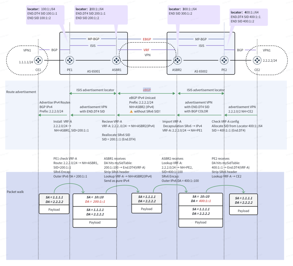
In this model, service traffic is decapsulated at the ASBR boundary. After a local VRF routing lookup, the traffic is forwarded through the network on the other side.
For example, consider IPv4 service traffic traveling from CE1 to CE2:
- PE1 uses VPN routing information to encapsulate the service packet into an SRv6 tunnel directed toward ASBR1.
- ASBR1 performs decapsulation based on its local service SID and forwards the original IPv4 packet into the corresponding VRF.
- ASBR1 forwards the original IPv4 packet to ASBR2 through the inter-domain interface.
- ASBR2 performs a route lookup in the corresponding VRF and re-encapsulates the packet into an SRv6 tunnel directed toward PE2.
- PE2 decapsulates the service packet and forwards it to CE2.
The main advantage of Option A is its clearly defined inter-domain boundaries. Different Autonomous Systems can maintain relatively independent Underlay networks and service control planes, making this model suitable for network migration, heterogeneous network interconnection, and environments requiring strict segmented management. However, it also has clear limitations: ASBRs must maintain tenant VRFs and handle decapsulation, routing lookups, and re-encapsulation. As the number of tenants increases, VRF scale, interface resources, and routing table size can become important scalability considerations.
4.3 Option B: Relay SID and Inter-Domain SID Translation
Option B uses Relay SIDs and SID Translation to enable service forwarding between different Autonomous Systems.Unlike Option A, Option B does not require ASBRs to create a separate VRF for every tenant. Instead, ASBRs can exchange VPN routes through MP-eBGP and maintain global BGP VPN routes and Transit lookup state for inter-domain forwarding.
Its key mechanisms include:
- The intra-domain IGP advertises only the Locators within its own domain.
- ASBRs exchange relevant VPN routes through MP-eBGP.
- Boundary nodes allocate local Relay SIDs.
- The outer IPv6 Destination Address is rewritten based on Transit lookup results.
- The inner service packet is preserved during forwarding, without requiring full service decapsulation and re-encapsulation at every boundary.
Typical logical architecture:
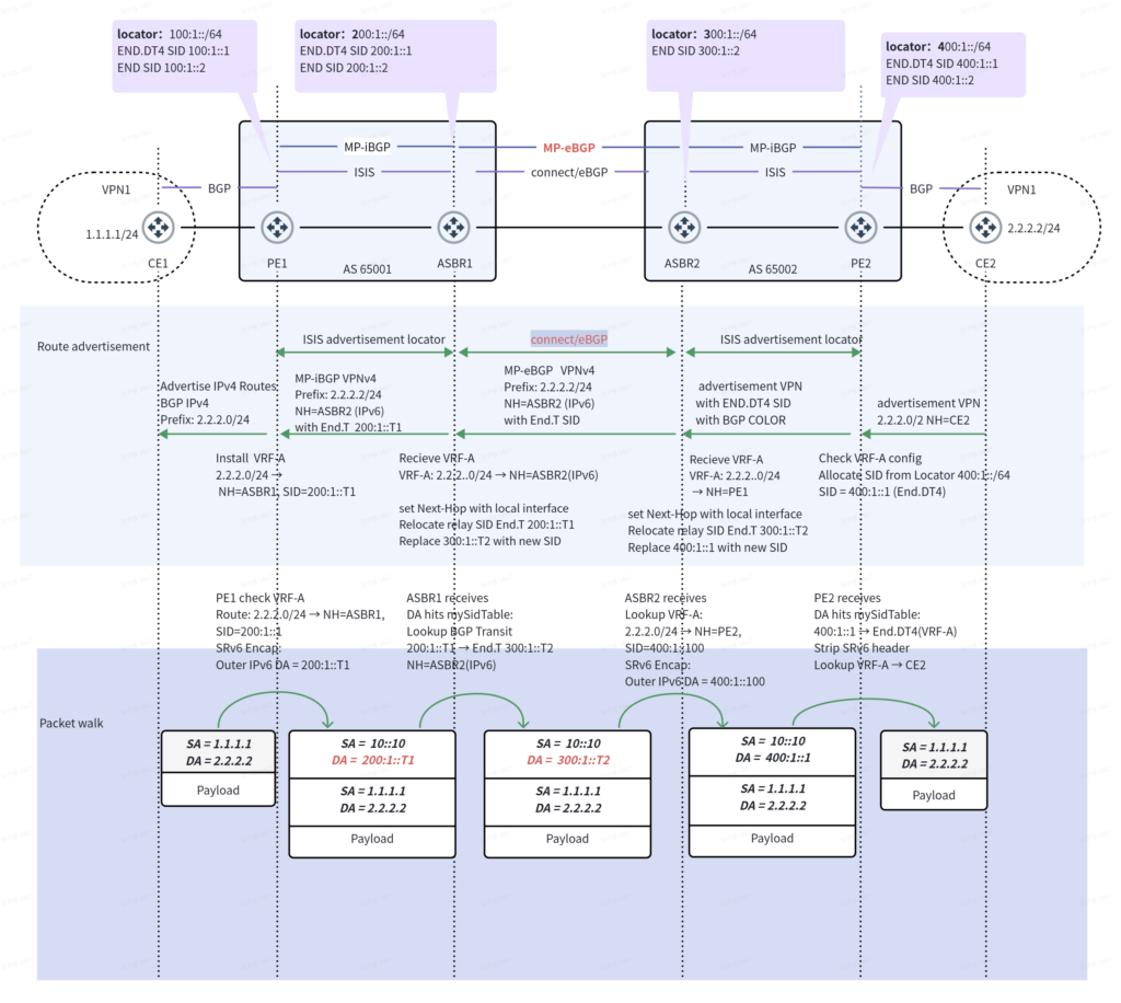
Using the IPv4 VPN example from Asterfusion’s whitepaper, the remote PE2 allocates an End.DT4 Service SID for the service route. When the route is propagated upstream through ASBR2 and ASBR1 toward PE1, the boundary nodes allocate corresponding Relay SIDs and update the SID information advertised to upstream nodes.
In the data plane:
- PE1 uses the service route information to encapsulate the original IPv4 packet into an IPv6 packet, with the outer destination address pointing to the Relay SID of ASBR1.
- ASBR1 matches its local Relay SID and rewrites the outer IPv6 destination address to the Relay SID of ASBR2 based on the Transit lookup result.
- ASBR2 performs another SID translation, rewriting the destination address to the final Service SID of PE2.
- PE2 performs decapsulation and VRF routing lookup based on End.DT4, completing service delivery.
Throughout the inter-domain forwarding process, the original IPv4 packet does not need to be recovered at every ASBR. The value of Option B lies in reducing the need for boundary nodes to maintain tenant-specific VRFs while preserving routing-domain isolation between different Autonomous Systems. It is suitable for networks requiring inter-AS connectivity, supporting a large number of tenants, or seeking to hide internal PE Locators. However, this model still requires boundary nodes to maintain VPN routes, Relay SID mappings, and Transit forwarding state. The relevant hardware resources and forwarding behaviors must therefore be carefully evaluated.
4.4 Option C: End-to-End Seamless SRv6
Option C adopts an end-to-end SRv6 service connectivity model.
Compared with the previous two models, its most important characteristic is: Intermediate ASBRs no longer perform tenant VPN service processing. Instead, they perform standard Layer 3 forwarding based on the outer IPv6 destination address.
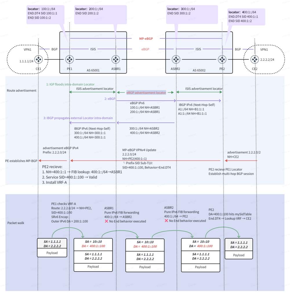
In Option C, PEs in different Autonomous Systems can exchange VPN routes through multi-hop MP-eBGP or inter-domain Route Reflectors. At the same time, the network must ensure that remote PE Locators are reachable across the inter-domain Underlay. A typical forwarding process is as follows:
- PE2 allocates a Service SID for the remote service and advertises the corresponding service route to PE1 through MP-eBGP.
- Based on the routing information, PE1 directly encapsulates the service packet using PE2’s Service SID.
- As the packet traverses ASBR1, ASBR2, and other intermediate routers, these devices perform routing lookups based only on the outer IPv6 destination address.
- Intermediate ASBRs do not perform tenant VRF lookups and do not need to reallocate or rewrite the Service SID.
- When the packet reaches PE2, the PE executes the corresponding SRv6 Endpoint Behavior to decapsulate and forward the service packet.
Option C centralizes service state at the PE endpoints while simplifying the intermediate network into an IPv6 forwarding infrastructure. This design helps reduce service-processing complexity at intermediate boundary nodes and provides a unified network foundation for end-to-end service paths and SRv6 policies. However, Option C places higher requirements on inter-domain IPv6 Locator reachability and coordination between network control planes. It is suitable for large-scale data center or cloud networks with unified IPv6 planning that aim to simplify service state on intermediate nodes.
4.5 How to Choose Among the Three SRv6 DCI Models?
There is no absolute winner among the three models.
- Option A emphasizes segmented isolation and network compatibility.
- Option B balances inter-domain isolation with the scale of state maintained at boundary nodes.
- Option C focuses on end-to-end SRv6 connectivity and simplified forwarding at intermediate nodes.
The appropriate choice should be based on tenant scale, Autonomous System boundaries, IPv6 planning, hardware forwarding capabilities, and operational requirements.
Further Reading: Asterfusion SRv6 DCI Deployment: Three Inter-Domain Deployment Modes Explained
4.6 SRv6 Traffic Engineering and Path Control
In addition to inter-domain service connectivity, SRv6 can also be combined with Traffic Engineering (TE) to enable policy-based path control. In DCI environments with multiple available network paths, network designers can use SRv6 Policy and Segment Lists to define specific forwarding paths for designated services. AsterNOS’s relevant feature list includes SRv6 Best Effort and Static SRv6 TE Policy.
For example, a cross-site network may simultaneously carry database replication, backup traffic, and application traffic with different priority levels. In deployments that support the corresponding SRv6 TE capabilities, predefined policies can be used to control the network paths taken by specific traffic flows.
SRv6 TE design also requires consideration of the following factors:
- SID and Segment List planning.
- Mapping between policies and service traffic.
- IPv6 Underlay reachability.
- Path redundancy and failure recovery.
- Encapsulation overhead and MTU.
- ASIC support for forwarding the corresponding SRv6 behaviors.
Asterfusion’s SRv6 DCI whitepaper also discusses advanced technologies such as Flow Label-based load balancing, Flex-Algo, BSID, TI-LFA, and SLA-driven path orchestration.
These technologies provide valuable references for network evolution and solution design. However, their availability in specific deployments must still be verified against the relevant AsterNOS software version and hardware platform.
5. 400G/800G Optical DCI: ZR/ZR+ and IPoDWDM
Regardless of whether BGP, EVPN-VXLAN, or SRv6 is used, inter-data-center traffic ultimately needs to be carried over a physical transport network. As demand for cloud services, AI computing, and large-scale data replication continues to grow, high-speed 400G/800G connectivity is becoming an important technology direction for high-capacity DCI networks.
5.1 Traditional Optical Transport Architecture for DCI
Traditional optical interconnect architectures typically connect switches to dedicated optical transport equipment, which then uses a DWDM network to provide connectivity between sites.
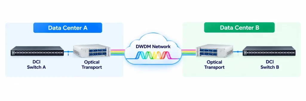
This architecture leverages specialized optical transport equipment to provide long-distance connectivity. However, it also increases the number of devices, management systems, and network layers.
5.2 IPoDWDM: High-Speed Interconnectivity Using Coherent Optical Modules
IP over DWDM (IPoDWDM) combines IP routing or switching equipment with DWDM optical transport technology. On compatible platforms, coherent optical modules such as 400G/800G ZR/ZR+ can be used to connect high-speed switch ports directly to suitable fiber links or DWDM transport systems.
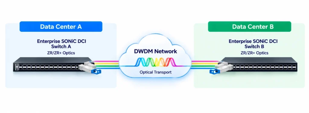
This architecture can reduce the need for standalone transponder equipment, simplify the network architecture, and lower equipment and operational complexity in certain deployment scenarios. However, having 400G/800G ports on a high-speed switch does not automatically mean that the switch supports the corresponding ZR/ZR+ coherent optical modules. Actual deployments must evaluate factors such as module power consumption, thermal requirements, FEC, software compatibility, optical reach, and link budget.
5.3 How Does IPoDWDM Work with EVPN-VXLAN and SRv6?
IPoDWDM provides high-capacity optical transport at the physical layer, while EVPN-VXLAN and SRv6 provide different approaches to network virtualization, routing, and service forwarding. These technologies operate at different layers and can be combined according to the requirements of the DCI architecture. EVPN-VXLAN and SRv6 are alternative network approaches rather than technologies that must be deployed together.
| Technology | Primary Function |
|---|---|
| BGP | Routing information exchange between network domains |
| EVPN-VXLAN | Overlay network virtualization and tenant connectivity |
| SRv6 | IPv6-based programmable forwarding, inter-domain connectivity, and path control |
| IPoDWDM | High-capacity optical transport over DWDM infrastructure |
| ZR/ZR+ | Coherent optical interfaces for high-speed data transmission |
For example, a multi-site network using an SRv6 Option C architecture can leverage compatible ZR/ZR+ coherent optical interfaces over an IPoDWDM infrastructure to provide high-bandwidth physical connectivity. At the network layer, an IPv6 underlay provides reachability between SRv6 endpoints (SIDs). Service packets are encapsulated with SRv6 at the ingress PE, forwarded across the IPv6 network according to the SRv6 forwarding information, and decapsulated at the egress PE.
In this design, the optical transport infrastructure provides the physical connectivity and bandwidth, while SRv6 handles service-level forwarding and traffic engineering. Similarly, EVPN-VXLAN-based DCI architectures can also use IPoDWDM and compatible coherent optical interfaces to connect geographically separated data center fabrics. Combining high-speed optical interconnects with flexible network architectures gives data centers more options for building scalable and efficient DCI infrastructure.
6. DCI High Availability, Security, and Network Observability
DCI networks typically carry inter-site services, data replication traffic, and mission-critical application traffic. Network reliability and operational visibility are therefore equally important.
6.1 BFD and Fast Failure Detection
BFD can work alongside routing protocols such as BGP, OSPF, and IS-IS to help rapidly detect supported link or neighbor failures. When a failure occurs, the associated routing protocol can recalculate routes or select an available alternative path. Actual recovery time depends on the network topology, protocol configuration, hardware forwarding table updates, and service-level resilience mechanisms.
6.2 ECMP and Redundant DCI Design
For DCI networks with multiple equal-cost paths, ECMP can distribute traffic across available paths. Redundant Border Leaf switches or DCI switches can also help reduce the risk of single points of failure. In SRv6 networks, primary and backup paths can be further planned according to the supported path policies and forwarding mechanisms, providing traffic protection and failure recovery.
6.3 VRF, ACL, and QoS
Multi-site networks may carry traffic for multiple tenants, applications, and services with different priority levels. Enterprise SONiC can use mechanisms such as VRF, ACL, QoS, and Routing Policy to provide routing domain isolation, access control, and traffic management.
For SRv6 DCI, service isolation must also be evaluated in the context of the selected Option A/B/C architecture, including VPN route state, SID behavior, and inter-domain boundary processing.
6.4 Automation and Network Observability
As DCI networks continue to scale, cross-site configuration management, traffic monitoring, performance analysis, and troubleshooting become increasingly complex. AsterNOS Enterprise SONiC provides open management interfaces and supports integration with network telemetry and visualization tools, helping operators build a more automated network operations framework.
Key capabilities include:
- CLI / SSH: Device configuration, status queries, and troubleshooting.
- REST API, NETCONF/YANG, and gNMI: Configuration management, automation integration, and network state retrieval.
- SNMP: Collection of device status, interface statistics, and performance metrics.
- sFlow: Sampling-based network traffic analysis.
- INT (In-band Network Telemetry): Provides fine-grained data-plane telemetry on supported hardware platforms, helping analyze forwarding paths, congestion, and network performance.
- Prometheus: Centrally collects and stores network metrics exposed through compatible exporters or monitoring interfaces.
- Grafana: Builds visualization dashboards using data sources such as Prometheus to display interface utilization, device status, and network performance trends.
- Syslog: Centralized recording of system events and alerts.
- ZTP: Supports automated device initialization and deployment.
For BGP, EVPN-VXLAN, and SRv6 DCI networks, observability should cover more than interface traffic and device status. It should also include:
- Underlay routing and BGP neighbor status.
- EVPN routes and VXLAN tunnel status.
- SRv6 Locator, SID, and Policy status.
- Link utilization and traffic distribution.
- Packet loss, congestion, and related performance metrics.
- Failure events and routing convergence processes.
When the required data collection and integration capabilities are available, INT, Prometheus, and Grafana can complement one another: INT provides fine-grained data-plane information, Prometheus handles metric collection and storage, and Grafana enables visualization and analysis. This multi-layered approach to network observability helps improve DCI fault isolation, capacity planning, and day-to-day network operations.
7. High-Precision Time Synchronization (PTP / SyncE)
Asterfusion’s 1G–800G switches support IEEE 1588v2 PTP, with synchronization capabilities for 5G O-RAN/xHaul (ITU-T G.8275.x), broadcast media (SMPTE ST 2059-2 / AES67), and general campus/data center networks (IEEE 1588v2), subject to model and software configuration. The CX306P-48Y-M-H additionally supports SyncE and GNSS and has been selected for a real-world customer project involving inter-data-center time synchronization.
8.Asterfusion Enterprise SONiC FOR DCI Platforms
Asterfusion AsterNOS is an enterprise-grade network operating system based on SONiC, providing a comprehensive set of routing, network virtualization, and management capabilities for data centers, enterprise networks, and high-performance infrastructure.
With switching platforms offering different port speeds and densities, Asterfusion can design DCI solutions tailored to customers’ bandwidth requirements, network protocols, and optical interconnect needs.
| Model | Ports | EVPN-VXLAN Multi-Site DCI | Integrated EVPN Multi-Site Gateway | SRv6 | PTP / SyncE | ZR/ZR+ |
| CX864E-N | 64 × 800G | Partial | On Roadmap | On Roadmap | Class C-capable | Up to 32 |
| CX764QD-N / CX764QO-N | 64 × 400G | Partial | On Roadmap | On Roadmap | Class C-capable | Up to 32 |
| CX764QH-N | 64 × 400G | Partial | To Be Confirmed | Yes | On Roadmap | No |
| CX732Q-N (Marvell Teralynx 7) | 32 × 400G | Partial | On Roadmap | No | No | Up to 16* |
| CX732Q-N-V2 (Marvell Falcon) | 32 × 400G | Partial | On Roadmap | No | Class C-capable | Up to 16* |
| CX664D-N | 64 × 200G | Partial | On Roadmap | No | No | Up to 16 |
| CX564P-N | 64 × 100G | Partial | On Roadmap | No | No | Up to 16 |
| CX532P-N | 32 × 100G | Partial | On Roadmap | No | No | Up to 8 |
| CX532P-N-V2 | 32 × 100G | Partial | On Roadmap | No | Yes | Up to 8 |
| CX732Q-M-H | 32 × 400G | Partial | No | Yes | Class C-capable | Up to 16 |
| CX532P-M-H | 32 × 100G | Partial | No | Yes | Class C-capable | Up to 8 |
| CX308P-48Y-M-H | 48 × 25G + 8 × 100G | Partial | No | Yes | Class C-capable | No |
| CX306P-48Y-M-H | 48 × 25G + 6 × 100G | Partial | No | Yes | Class C + Optional GNSS | No |
9. How to choose Asterfusion Enterprise SONiC DCI Platforms
9.1. Traditional Layer 3 DCI (Routed DCI)
Use Case: Connecting Multiple Data Centers Through IP Routing.In simple terms: Connecting two or more data centers through an IP network, allowing servers, business systems, and storage resources at different sites to communicate with each other.
- Target Customers: Enterprise data centers, cloud service providers, and telecom operators.
- Typical Requirements: Inter-data-center communication, data synchronization, and disaster recovery connectivity.
- Key Technologies: BGP, IPv4/IPv6 Routing.
- Key Selection Criteria: Routing table capacity, BGP support, port bandwidth, and forwarding performance. For deployments requiring larger routing tables, Marvell Falcon-based platforms are recommended.
Recommended Products:
- CX-N Series: Suitable for high-bandwidth Layer 3 DCI deployments.
- CX-N-V2 Series: Based on the Marvell Falcon platform, suitable for deployments with higher routing table capacity requirements. (CX732Q-N-V2,CX532P-N-V2)
- CX732Q-M-H,CX532P-M-H,CX308P-48Y-M-H,CX306P-48Y-M-H
9.2. EVPN-VXLAN Multi-Site DCI
In simple terms: Beyond enabling communication between data centers, EVPN-VXLAN allows virtual machines and tenant networks across different sites to connect, supporting workload migration and network extension between data centers.
- Target Customers: Large enterprises, cloud service providers, and multi-data-center operators.
- Typical Requirements: Connecting virtual machines across data centers, extending tenant networks, and supporting workload migration.
- Key Technologies: BGP EVPN, VXLAN, Multi-Site Gateway.
- Key Selection Criteria: In addition to basic EVPN-VXLAN capabilities, verify whether the required Multi-Site Gateway functions are fully supported.
Recommended Products: CX864E-N,CX764QD-N,CX764QO-N,CX732Q-N
Note: These models currently support selected EVPN-VXLAN Multi-Site DCI functions. Full integrated Multi-Site Gateway functionality remains subject to the product roadmap. They should not be positioned as fully integrated BGW solutions.
9.3. SRv6-Based DCI
In simple terms: Connecting different data centers over an IPv6 network while using SRv6 to provide more flexible control over the paths that data traffic takes.
- Target Customers: Telecom operators, cloud service providers, and large network service providers.
- Typical Requirements: Cross-regional data center interconnection, IPv6 backbone networking, and flexible traffic path control.
- Key Technologies: IPv6, SRv6, BGP.
- Key Selection Criteria: SRv6 support, routing scale, forwarding performance, and port bandwidth.
Recommended Products:
- CX764QH-N: 64×400G, supports SRv6.
- CX732Q-M-H: 32×400G, supports SRv6.
- CX532P-M-H: 32×100G, supports SRv6.
- CX308P-48Y-M-H: 48×25G + 8×100G, supports SRv6.
- CX306P-48Y-M-H: 48×25G + 6×100G, supports SRv6.
9.4. Long-Distance / Coherent Optical DCI
In simple terms: Connecting geographically distant data centers over optical fiber using high-speed optical modules, such as 400G or 800G links between sites in different cities or regions.
- Target Customers: Inter-city data centers, cloud service providers, Neocloud providers, and AI data centers.
- Typical Requirements: Long-distance, high-bandwidth data transmission.
- Key Technologies: 400G/800G ZR, ZR+, Coherent Optics, IPoDWDM.
- Key Selection Criteria: ZR/ZR+ module support and port count, transmission distance, fiber conditions, optical power budget, and equipment compatibility.
Recommended Products:
- CX864E-N: Supports up to 32 ZR/ZR+ interfaces.
- CX764QD-N / CX764QO-N: Supports up to 32.
- CX732Q-N / CX732Q-N-V2: Supports up to 16.
Note: The actual number of supported interfaces depends on the optical module specifications, link conditions, and device configuration.
9.5. PTP-Based DCI (Precision Time Synchronization)
In simple terms: In addition to exchanging data, devices across different data centers or network locations need to maintain highly accurate time synchronization and share a consistent time reference.
- Target Customers: Data centers with demanding time synchronization requirements,5G/O-RAN operators, broadcasting organizations and financial institutions.
- Typical Requirements: Cross-site time synchronization, precise timestamping, and network clock synchronization.
- Key Technologies: IEEE 1588v2, PTP, T-GM, T-BC, T-TSC, GNSS.
- Key Selection Criteria: PTP accuracy class, clock modes, GNSS connectivity, and ingress/egress delay compensation.
Recommended Products:
- CX864E-N: Class C-capable.
- CX764QD-N / CX764QO-N: Class C-capable.
- CX732Q-N-V2: Class C-capable.
- CX732Q-M-H: Class C-capable.
- CX532P-M-H: Class C-capable.
- CX308P-48Y-M-H: Class C-capable.
- CX306P-48Y-M-H: Class C-capable, with optional GNSS support.
DCI Scenarios and Asterfusion Product Recommendations
| DCI Scenario | Typical Use Cases | Target Customers | Key Technologies | Key Selection Criteria | Recommended Asterfusion Models |
|---|---|---|---|---|---|
| 1. Traditional Layer 3 DCI (Routed DCI) | Connecting multiple data centers through IP routing for application access, data synchronization, and disaster recovery. | Enterprise data centers, cloud service providers, telecom operators. | BGP, IPv4/IPv6 Routing | Routing table capacity, BGP support, port bandwidth, forwarding performance. For larger routing table requirements, consider Marvell Falcon-based platforms. | CX-N Series: CX732Q-N-V2 CX532P-N-V2 CX732Q-M-H, CX532P-M-H CX308P-48Y-M-H CX306P-48Y-M-H |
| 2. EVPN-VXLAN Multi-Site DCI | Extending virtual networks and tenant connectivity across data centers, enabling workload migration between sites. | Large enterprises, cloud service providers, multi-data-center operators. | BGP EVPN, VXLAN, Multi-Site Gateway | EVPN-VXLAN feature support, Multi-Site Gateway capabilities, route handling, and inter-site connectivity requirements. | CX-N Series |
| 3. SRv6-Based DCI | Connecting data centers over IPv6 networks with flexible traffic path control. | Telecom operators, cloud service providers, large network service providers. | IPv6, SRv6, BGP | SRv6 support, routing scale, forwarding performance, and port bandwidth. | CX732Q-M-H, CX532P-M-H, CX764QH-N |
| 4. Long-Distance / Coherent Optical DCI | High-bandwidth optical interconnection between geographically distant data centers, such as sites in different cities or regions. | Inter-city data centers, cloud service providers, Neocloud providers, AI data centers. | 400G/800G ZR, ZR+, Coherent Optics, IPoDWDM | ZR/ZR+ module support, maximum port count, transmission distance, fiber conditions, optical power budget, and equipment compatibility. | CX864E-N, CX764QD-N, CX764QO-N, CX732Q-N, CX732Q-N-V2 CX732Q-M-H, |
| 5. PTP-Based DCI (Precision Time Synchronization) | Maintaining highly accurate time synchronization across data centers and network locations. | 5G/O-RAN operators, broadcasting organizations, financial institutions, time-sensitive data centers. | 5G O-RAN / xHaul ITU-T G.8275.x Broadcast Media SMPTE ST 2059-2 / AES67 Data Center Interconaction IEEE 1588v2 | PTP accuracy class, clock modes, GNSS connectivity, ingress/egress delay compensation. For more: Precision Time Protocol PTP Switches | CX864E-N; CX764QD-N / CX764QO-N; CX732Q-N-V2; CX532P-M-H, CX732Q-M-H CX308P-48Y-M-H,; CX306P-48Y-M-H, (optional GNSS) |
Building Scalable and Flexible DCI Networks with Enterprise SONiC
There is no one-size-fits-all approach to Data Center Interconnect. Different deployments have different requirements, from traditional Layer 3 routing and EVPN-VXLAN Multi-Site to SRv6-based traffic engineering, 400G/800G coherent optical connectivity, and precision time synchronization.
The right DCI architecture should deliver the bandwidth, performance, and reliability required today while providing the flexibility to scale as network demands evolve. Equally important is choosing an open and adaptable networking platform that avoids unnecessary complexity and proprietary vendor lock-in.
Powered by AsterNOS Enterprise SONiC, Asterfusion’s 1G–800G switching portfolio provides flexible hardware and software options for diverse DCI architectures. With support for BGP routing, EVPN-VXLAN, SRv6, PTP, and high-speed ZR/ZR+ optical connectivity on selected platforms, Asterfusion helps enterprises, cloud providers, and network operators build high-performance, scalable, and adaptable inter-data center networks.
Planning your next DCI deployment? Contact Asterfusion to explore the right Enterprise SONiC switching solutions for your network architecture, routing requirements, and bandwidth needs.


