Table of Contents
What is MTU?
Before diving into Jumbo Frames, let’s first understand MTU.
MTU (Maximum Transmission Unit) is the largest packet size that can be transmitted over a network link without fragmentation. It is typically measured in bytes.
For standard Ethernet networks, the default MTU is 1500 bytes (1500B). This value usually refers to the maximum size of the IP packet (IP payload plus IP header) that can be carried in a single Ethernet frame. In some cases, the MTU can also be configured to a value smaller than 1500 bytes.
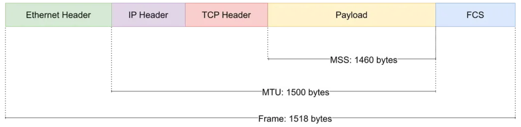
MSS: Maximum Segment Size. MSS refers to the maximum amount of TCP payload that can be carried in a single TCP segment.
When a packet exceeds the MTU of a network link, it cannot be transmitted as a single packet. Depending on the outgoing interface configuration and the packet’s Don’t Fragment (DF) flag, the packet is either fragmented into multiple IP packets or discarded.

Assume Host A needs to send data to Host B.
Host A first constructs the packet. The upper-layer protocol passes the data to the IP layer, which prepares an IP datagram for transmission.
Before sending the packet, the IP layer checks the MTU of the outgoing interface. If the packet size exceeds the interface MTU, the IP layer determines whether fragmentation is allowed. If fragmentation is permitted, the original IP datagram is divided into multiple fragments. Each fragment contains its own IP header. The receiving host reassembles the original packet using the Identification, More Fragments (MF) flag, and Fragment Offset fields in the IP header.
If fragmentation is not allowed, or the packet has the DF flag set, the packet is dropped instead. In most cases, the router returns an ICMP “Fragmentation Needed” message to the sender. If ICMP messages are blocked, Path MTU Discovery (PMTUD) cannot detect the MTU limitation, which may result in a PMTU black hole where packets are silently discarded.
What Happens When Using a Standard 1500-Byte MTU in High-Bandwidth Networks?
The standard 1500-byte MTU was conceived in an era of 10 Mbps shared-media Ethernet, designed to balance serialization delay and error rates over slow, lossy links.
Today, whether in an AI data center fabric running 400G/800G clusters, an enterprise core data center executing massive storage replication, or a modern campus backbone handling thousands of concurrent high-definition media streams, forcing modern high-speed infrastructure to slice traffic into legacy 1500-byte pieces exposes major architectural bottlenecks.
- Packet Rate Escalation Plagues Network Asics (Beyond NIC Offloads)
On 100G, 400G, or 800G links, a 1500-byte MTU forces an astronomical number of Packets Per Second (PPS) onto the wire.
Why Host-Level Offloads Aren’t Enough: Modern servers utilize advanced features like TSO (TCP Segmentation Offload) and GRO (Generic Receive Offload) to offload packet processing from the host CPU to the NIC hardware. However, this offload boundary ends at the server’s OS. Once the packets leave the server, the intermediate network switches, routers, and network virtual appliances (NVAs) must process every single packet header at the ASIC level.
An excessive PPS rate stresses the switch forwarding engine, drives up lookup overhead, and rapidly consumes the switch’s on-chip buffer space.
- Protocol Header Overhead and Diminishing Payload Efficiency
Every packet carries layered encapsulation overhead. At 1500 bytes, the relative cost of protocol headers is significantly amplified. For standard TCP/IP traffic, the L4/L3 headers take up a fixed 40 bytes. When deep packet inspection (DPI) platforms, monitoring brokers, or storage protocols are in play, this overhead grows.
Mathematically, a 1500-byte MTU caps the maximum TCP payload size (MSS) at 1460 bytes (1500 – 20 IP – 20 TCP), meaning roughly 2.67% of line-rate bandwidth is wasted strictly on L3/L4 protocol headers before even accounting for L2 Ethernet frame framing (Preamble, Interpacket Gap, FCS). For data-intensive applications—like distributed database replication, storage area networks (SAN), and AI model weight exchanges—this overhead scales up to gigabytes of pure waste, preventing the physical link from reaching its true theoretical throughput.
- Increased Vulnerability to Micro-bursts and Congestion Control Stress
High-throughput environments are highly sensitive to latency variation and packet drops. When large data payloads are fragmented into millions of 1500-byte packets, they hit switch queues in aggressive waves, commonly known as micro-bursts.
In enterprise and AI Ethernet fabrics utilizing congestion management protocols like ECN (Explicit Congestion Notification) and PFC (Priority Flow Control), a dense storm of small packets causes switch buffers to fill erratically.
This triggers frequent ECN marking or PFC pause frames, which artificially throttles network throughput, injects queuing jitter, and destabilizes time-sensitive traffic (such as storage heartbeats, control plane messages, or GPU synchronization).
- Tunnel Encapsulation Risks: PMTUD Black Holes in Multi-Tenant Networks
Modern networks—ranging from multi-tenant enterprise campuses to hybrid cloud data centers—rely heavily on network virtualization and overlay overlays like VXLAN, EVPN, and SRv6. These technologies wrap original packets in additional headers (e.g., VXLAN adds a 50-byte encapsulation overhead).
If the underlying physical network is rigidly locked at a 1500-byte MTU, an encapsulated 1500-byte packet will immediately exceed the frame limit, triggering two devastating scenarios:
- PMTU Black Holes: Path MTU Discovery (PMTUD) relies on ICMP “Fragmentation Needed” messages to negotiate size dynamically. In real-world enterprise architectures, security firewalls frequently drop or filter ICMP traffic. Consequently, large payload flows are silently discarded by the network while small packets (like ICMP pings) pass through cleanly, leaving engineers with complex, invisible connectivity timeouts that are notoriously difficult to troubleshoot.
- IP Fragmentation: Forcing intermediate devices or end-hosts to segment and reassemble packets, which massively degrades processing performance.
- Multi-Domain Vulnerability to MTU Mismatch
As enterprise infrastructures evolve into complex environments spanning Kubernetes clusters, software-defined networks (SDN), load balancers, and third-party security appliances, the forwarding path grows longer. If even a single transit node or virtual interface along this path defaults to a lower MTU, it creates a performance bottleneck for the entire transit fabric.
While legacy traditional web traffic can absorb these inefficiencies through TCP retransmissions, modern data center operations, distributed campus backbones, and synchronized cluster computation require deterministic, high-throughput, low-latency performance that a standard 1500-byte MTU simply cannot sustain.
What is a Jumbo Frame and Where is it Deployed?
A Jumbo Frame is an Ethernet frame that exceeds the standard 1500-byte MTU defined by IEEE 802.3. In AI data centers, Jumbo Frames are typically enabled by configuring the MTU (Maximum Transmission Unit) to 9000 bytes or higher.
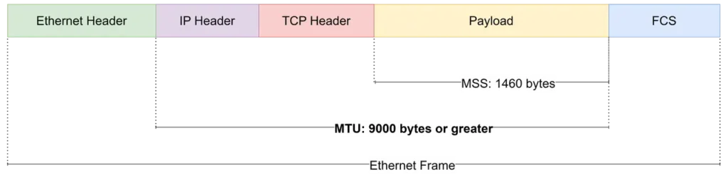
Jumbo Frames are widely used in storage networks, HPC clusters, and AI data centers where large volumes of data are transferred continuously.
Note: An MTU of 9,000 bytes is a widely adopted engineering convention rather than an IEEE-defined Jumbo Frame standard.
Where Are Jumbo Frames Deployed?
The operational advantages of Jumbo Frames—reducing packet counts, cutting header overhead, and streamlining switch buffer allocation—make them a baseline architecture across multiple high-throughput network domains.
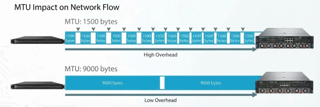
Campus Core Networks: Handles massive concurrent East-West and North-South traffic from 4K/8K video conferencing and high-volume cloud syncs. Enabling Jumbo Frames expands the effective “pipe diameter,” ensuring large data streams achieve smooth, fragmentation-free line-rate forwarding.
Backbone & Core Routers: While end-hosts utilize hardware offloads, routers must still process every single packet header at the ASIC level. Jumbo Frames reduce data plane packet rate and per-packet overhead for NICs, software datapaths, NVAs, DPI, and nodes requiring per-packet processing.
Storage Area Networks (SAN): Protocols like iSCSI and NAS natively transport data in large blocks ($\ge$ 4KB). Configuring an end-to-end 9000 MTU prevents data blocks from being aggressively fragmented at the source, significantly shortening backup windows and boosting IOPS.
AI & HPC Clusters: Distributed GPU training over 400G/800G RoCEv2 networks requires continuous, synchronous parameter exchanges. Jumbo Frames minimize protocol header overhead and deliver deterministic, ultra-low latency, preventing the cluster from stalling due to packet fragmentation drops.
Technical Deconstruction: Understanding the Boundaries of L3 MTU vs. L2 Frame Size
One of the most frequent points of confusion for network engineers when adopting Jumbo Frames is the relationship between the Layer 3 MTU configured on an operating system and the actual Layer 2 Frame Size handled by switch hardware. Terms like MTU, Payload, Frame Size, and Max Frame Size are often used interchangeably, leading to misconfigurations.
To prevent silent packet drops and configuration mismatches, we must break down how protocol headers consume byte space at different layers.
The following boundary and overhead comparison table tracks how a standard packet expands as it moves from the network layer down to the physical wire, comparing standard constraints against Jumbo configurations:
| Layer | Concept | Standard Size | Jumbo Configuration | Headers Included / Description |
| L3 (Network) | IP MTU / Payload | 1,500 Bytes | 9,000 Bytes | IP Header (20B) + TCP Header (20B) + Application Payload |
| L2 (Data Link) | Ethernet Frame Size | 1,518 Bytes | 9,018 Bytes | L3 IP MTU + Ethernet Header (14B) + Frame Check Sequence (FCS) (4B) |
| L2 (Tagged) | Dot1q Tagged Frame | 1,522 Bytes | 9,022 Bytes | Includes standard single-layer VLAN Tag (4B) overhead |
| Overlay | VXLAN Encapsulated | 1,550 Bytes | 9,050 Bytes | Outer Eth (14B) + Outer IP (20B) + Outer UDP (8B) + VXLAN Header (8B) |
| Switch ASIC | Max Frame Size / MRU | 1,522+ Bytes | 9,216 Bytes | Switch ASIC maximum ceiling, reserved for double-tagging (QinQ) or MPLS/SRv6 label stacks. |
Setting the Proper MTU in an AI Data Center Network
While Jumbo Frames bring performance advantages across campus, storage, and datacenter networks, their concrete implementation relies on a meticulous end-to-end configuration. To demonstrate how to verify and deploy this in a production environment, we will use an AI data center backend network as a representative scenario.
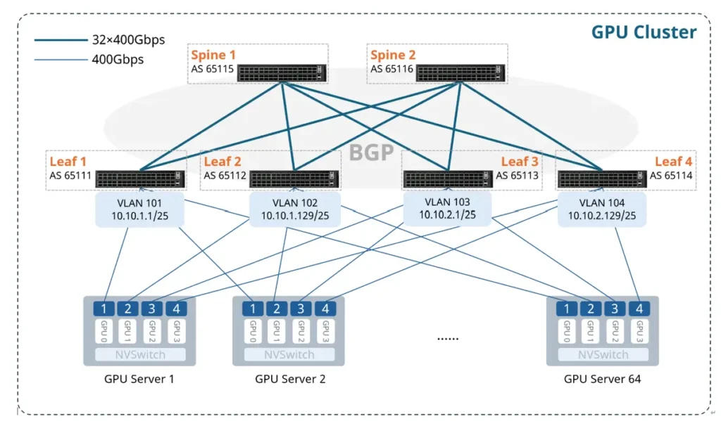
In a Rail-Optimized GPU Fabric built with the Asterfusion CX864E-N, the MTU directly affects the efficiency and stability of large-scale GPU communication. For a 400G RoCEv2 network, follow these engineering practices when configuring the MTU.
1. Maintain End-to-End MTU Consistency
In a GPU fabric, every device along the data path, including GPU NICs, local host OS interfaces, switch ports, and intermediate security gateways, must use an aligned MTU value.
- Supported range: 1312 to 9216 bytes in AI ethernet switches.
- Recommended setting: For 400G RoCEv2 backend computing fabrics, set the end-to-end payload MTU to 9000 bytes (which maps to the switch’s hardware limit of 9216 bytes to handle additional tunnel encapsulation budgets safely).
2. Map Your Network MTU Budget (Host-to-Fabric)
Before applying configurations blindly, you must account for overhead accumulation along the forwarding path to avoid unwanted dropping or fragmentation at overlay boundaries:
- Host OS / NIC Level: Configure the baseline L3 IP MTU to
9000. - ToR & Spine Switches: Set the global L2 MTU to
9216to provide an extra 216-byte safety margin for internal infrastructure tagging (such as standard Dot1q VLANs, QinQ, or MPLS/SRv6 labels). - Overlay Boundaries (VTEP / VXLAN): If traffic traverses an encrypted or virtualized overlay tunnel, remember that VXLAN encapsulation injects a fixed 50-byte header overhead. Ensure that the underlay transit physical fabric is explicitly set to
9216so that the encapsulated packet (9000 + 50 = 9050 bytes) flows cleanly through the hardware without exceeding transmission limits.
3. Hands-on Configuration & Verification Procedures
Do not rely on software assumptions. Use the following operational commands to configure and verify MTU alignments in production:
A. Host-Side Configuration & Diagnostics (Linux)
# Temporarily set the interface MTU to Jumbo mode (e.g., eth0)
sudo ip link set dev eth0 mtu 9000
# Verify the interface status and current MTU size
ip link show dev eth0
# Perform a strict end-to-end Jumbo verification ping
# Formula: 9000 (MTU) – 20 (IP Header) – 8 (ICMP Header) = 8972 Bytes
# (-M do forces the “Don’t Fragment” bit to test true path clearance)
ping -M do -s 8972
# Discover where the MTU drops along the path using tracepath
tracepath
B. Open Networking Switch Configuration (SONiC System)
# View current port physical status and MTU sizes
show interface summary
# View current L3 interface configurations
show ip interfaces
4. Hands-on Configuration & Verification Procedures
MTU misconfigurations rarely cause a complete network blackout. Instead, they manifest as elusive “grey failures.” Watch out for these three classic deployment symptoms:
- The “Ping Works, App Fails” Paradox: Small packets (such as standard ICMP pings or SSH control sessions) pass through perfectly because they sit well below the 1500-byte threshold. However, as soon as heavy application data flows (like GPU parameter synchronization or storage block transfers) attempt to scale up, the larger frames are silently dropped, causing connection timeouts.
- Asymmetric Data Black Holes: Traffic flows normally in one direction but drops entirely in the reverse. This indicates that one return-path switch or firewall along the asymmetrical transit loop is misconfigured back to a standard 1500-byte limit.
- PMTUD Black Holes via Filtering: Path MTU Discovery (PMTUD) relies entirely on intermediate routers sending back an ICMP Type 3 Code 4 (Fragmentation Needed) message if a packet is too large. If your security policies or firewalls explicitly block all ICMP traffic, the sender never receives this signal. The system experiences a PMTU Black Hole—oversized packets vanish silently without triggering down-scaling retransmissions.
5. Validate the Entire Forwarding Path
Configuring only the host servers and the first-hop ToR switch is never sufficient. Even if your edge devices are set perfectly, a single misconfigured spine switch, transit gateway, or security appliance further down the line will break the traffic loop. You must use the ping and tracepath utilities mentioned above to manually test and verify the entire end-to-end forwarding path.
If you are unsure of the exact syntax required to modify and verify the MTU boundaries on our network switches, please refer to the step-by-step commands outlined in our Interface Base Configuration guide. Ensure all switch-level configurations are applied before executing your live path validation tests.
Conclusion
As AI models continue to grow in size, network efficiency becomes increasingly important. A high-performance AI data center requires a network that delivers predictable performance with minimal overhead. Understanding MTU behavior and deploying Jumbo Frames with consistent end-to-end configuration helps eliminate unnecessary fragmentation, reduce packet processing overhead, and fully utilize GPU cluster performance.
When deploying an AI cluster, ensure that your network switches can process Jumbo Frames at line rate. If you are planning a large-scale GPU deployment, contact our networking experts to discuss your requirements and receive guidance on optimizing your AI network architecture.


