Table of Contents
What Is Packet Buffer?
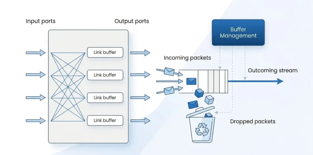
A packet buffer, also called a switch buffer, is temporary memory inside a switch that stores packets before they are forwarded. It absorbs burst traffic and handles short periods of congestion when an egress port cannot transmit packets immediately. Instead of dropping packets right away, the switch temporarily stores them in the packet buffer. Once bandwidth becomes available, the buffered packets are forwarded based on the configured scheduling policy.
For example, assume a 10G egress port is already transmitting traffic. If another burst of packets arrives and is destined for the same port, the port cannot send all packets at once. The newly arrived packets are temporarily stored in the packet buffer. After the earlier packets are transmitted and bandwidth becomes available, the buffered packets continue to be forwarded.
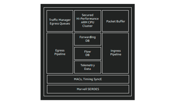
Packet buffer is a shared hardware resource at the switch level. All ports draw buffer space from the same memory pool. It is typically implemented in the switch ASIC’s MMU (Memory Management Unit) or a dedicated on-chip or adjacent packet buffer memory. The packet buffer absorbs traffic bursts, smooths traffic flow, and reduces packet loss during congestion. In production networks, the shared buffer is logically partitioned and allocated based on ports, queues, traffic classes, or priority levels to meet different QoS requirements.
Types of Packet Buffer
In AI data center switching ASICs, packet buffers are typically implemented as a physically shared memory pool, but are logically partitioned into multiple categories for different management and traffic handling purposes.
By direction:
Ingress buffer: Used when packets enter the switch from an ingress port. It mainly absorbs traffic bursts and prevents ingress congestion.
Egress buffer: Used when packets are ready to leave the switch through an egress port. It handles queuing and scheduling on the output side.
In many ASIC designs, ingress buffering is further divided into multiple Priority Groups (PGs), while egress buffering is split into multiple queues per port.
By function:
Guaranteed buffer: Reserved buffer space allocated to specific ports or queues. It ensures baseline forwarding capability under congestion conditions.
Shared buffer: A common pool that can be dynamically allocated across multiple ports and queues. It is used to absorb traffic bursts.
Headroom buffer: Used in lossless ingress scenarios, especially with PFC. It provides a safety margin before congestion backpressure takes effect. There is always a delay between downstream congestion detection and upstream traffic being paused. During this window, incoming packets are temporarily stored in the headroom buffer.
By traffic characteristics:
Lossless buffer: Designed for RoCE, storage, and AI training workloads where packet loss is unacceptable. It is typically combined with headroom buffering and PFC mechanisms.
Lossy buffer: Used for best-effort traffic. Packet loss is allowed under congestion, relying more on shared buffers and scheduling policies.
In real deployments, these buffer types are often combined into buffer profiles. For example, ingress buffer profiles for lossless traffic are configured separately to meet specific workload requirements.
Why AI Data Centers Care More About Packet Buffer
Packet buffering is a fundamental mechanism used in almost all network devices, including NICs, switches, and routers. It exists because real-world networks inevitably experience rate mismatches, bursty traffic, and short-lived congestion events.
However, compared with traditional Ethernet-based application workloads, AI data centers generate heterogeneous traffic patterns that are highly bursty and extremely sensitive to network instability. As a result, buffer design directly impacts tail latency, throughput stability, and packet loss rates.
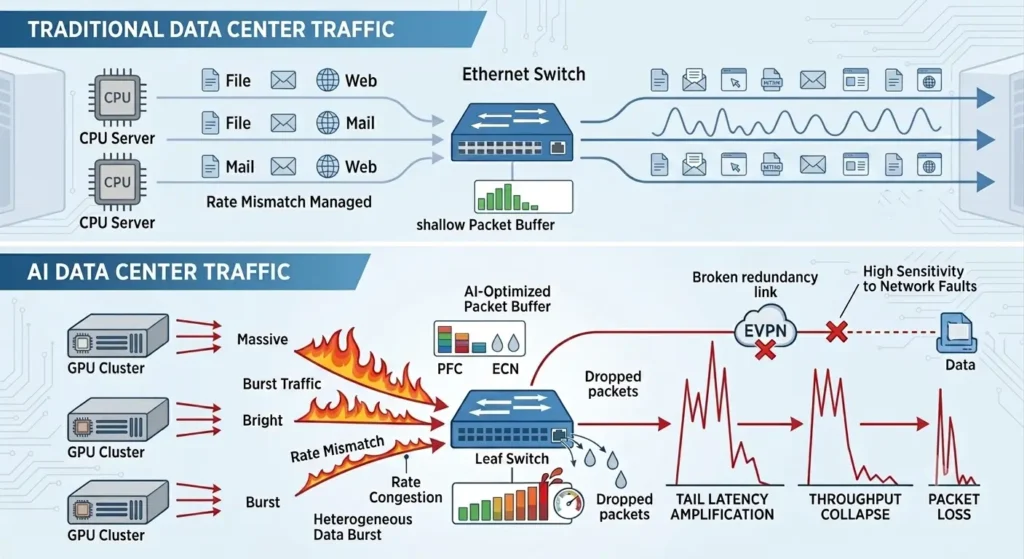
For example, when a leaf switch has insufficient packet buffer capacity, or when buffer allocation is not well aligned with microburst traffic patterns, multiple rack-scale GPU nodes may experience simultaneous queuing, packet drops, and amplified tail latency. This can significantly degrade the performance of All-to-All communication patterns.
Common Ethernet-based redundancy mechanisms, such as EVPN Multihoming, can improve link and device resiliency. However, if packet buffers cannot effectively absorb traffic bursts, performance collapse can still occur under high-concurrency training workloads.
Across AI front-end networks, AI back-end networks, and storage networks, packet buffering is a critical design factor. To learn more about these network layers,,refer to A Complete Guide to AIDC Storage Networks and The Fundamental Differences Between AI FrontEnd Networks and AI BackEnd Networks.
How Packet Buffer Buys “Golden Time” for Congestion Control
In AI data centers, packet buffer is often evaluated using a metric called Burst Absorption Time, which describes how long a switch can absorb transient traffic bursts without dropping packets.
Let’s take a 200 MB packet buffer as an example. If an 800G port is assumed to fully occupy the buffer under extreme conditions, we have: 200 MB÷100 GB/s=2 ms
This 2 ms represents the switch’s effective “survival window”. In other words, during short-lived congestion events such as incast, AllReduce, or microbursts, the buffer can temporarily hold backlogged traffic for about 2 ms before packet loss occurs.
Within this window, congestion control mechanisms such as ECN, PFC, and DCQCN can detect congestion and react accordingly. The buffer effectively decouples instantaneous traffic spikes from immediate packet loss, giving the control plane time to respond and adjust sending behavior.
Note: The 200 MB value refers to the total chip-level shared buffer. The calculation assumes a theoretical case where a single 800G port exclusively consumes the entire buffer, which is used only to illustrate burst absorption capability. In real deployments, usable buffer is influenced by multi-port contention, queue allocation policies, and shared pool arbitration, so the actual absorption time will vary under different traffic conditions.
How to Choose the Optimal Packet Buffer Size for Different Scenarios
Why bigger buffer is not always better ?
In essence, packet buffering trades latency for packet loss protection. For example, a ~2 ms buffer may be acceptable in a traditional data center. However, in AI training workloads, a deeper buffer can become a disadvantage. During large-scale congestion, packets may remain queued for extended periods, leading to queuing jitter. This additional latency, commonly referred to as bufferbloat, often has a greater negative impact on training efficiency than mild packet loss.
At the same time, hardware cost and power consumption must be considered. On-chip memory inside ASICs is expensive in both silicon area and energy usage. As buffer size increases, chip design becomes more complex and static power consumption rises accordingly. At hyperscale, where thousands of switches are deployed, these incremental power costs translate directly into significant OPEX.
Therefore, selecting an appropriate packet buffer is about finding a balanced point. The goal is to absorb typical AI microbursts and provide sufficient reaction time for congestion control mechanisms such as ECN and DCQCN, while keeping queuing delay as low as possible.
Asterfusion AI data center switches use Marvell ASICs. Based on different AI workload models and traffic characteristics, multiple buffering schemes are provided to support diverse network architectures:
SKU | Packet Buffer | Ports | Switching Capacity | Switch Chip |
200+ MB | 64×800G OSFP | 51.2 Tbps | Marvell Teralynx 10 | |
70 MB | OCP ORv3 400G QSFP-DD | 12.8 Tbps | Marvell Teralynx 7 | |
70 MB | 32×400G QSFP-DD | 12.8 Tbps | Marvell Teralynx 7 | |
70 MB | 64×200G QSFP56 | 12.8 Tbps | Marvell Teralynx 7 | |
70 MB | 64×100G QSFP28 | 6.4 Tbps | Marvell Teralynx 7 | |
70 MB | 32×100G QSFP28 | 3.2 Tbps | Marvell Teralynx 7 | |
48 MB | 32 x 400G QSFP-DD | 12.8 Tbps | Marvell Falcon | |
24 MB | 32×100G QSFP28 | 3.2 Tbps | Marvell Falcon | |
24 MB | 48×25G SFP28 + 8×100G QSFP28 | 2 Tbps | Marvell Falcon |
You can think of switches with different buffer depths as different sizes of traffic scheduling parking facilities:
A 200+ MB buffer is like a large-scale transportation hub with a massive parking structure. It is well suited for environments where microbursts, congestion absorption, and lossless flow control are frequent. Typical use cases include large-scale AI training clusters, RoCE-based networks, storage backends, and high-volume east-west traffic scenarios that require strong burst tolerance.
A 70 MB buffer resembles a medium-sized parking facility. It can handle moderate traffic bursts but does not provide deep buffering. It is generally suitable for enterprise-class or mid-scale AI training clusters and medium compute fabrics, where a balance between cost and performance is required.
A 48 MB buffer can be viewed as a compact yet balanced parking structure. It is designed for more regular traffic patterns but still requires a certain level of burst absorption capability. This fits smaller-scale compute nodes, inference-oriented workloads, or cost-sensitive entry-level training environments.
A 24 MB buffer is closer to a compact parking layout optimized for quick turnover. It is appropriate for low-to-moderate burst scenarios where ultra-deep buffering is not required, such as ToR access switches, general-purpose enterprise networks, and parts of the front-end network.
Overall, buffer size directly maps to the level of burst tolerance and congestion absorption required by different AI and data center traffic models.
Advanced QoS Technologies for Buffer Management
In addition to physical buffer capacity, efficient utilization of buffer resources requires fine-grained software-level scheduling and control.
Asterfusion integrates QoS, PFC mechanisms, and an AIDC intelligent operations platform to enable dynamic buffer adaptation across different traffic conditions.
QoS (Quality of Service): QoS queue mapping is used to differentiate lossy and lossless traffic. Based on traffic priority (such as RDMA flows versus management traffic), QoS provides precise bandwidth guarantees and controlled buffer allocation to ensure predictable performance.
PFC (Priority-based Flow Control): When buffer occupancy approaches critical thresholds, PFC triggers precise backpressure at the priority level. This mechanism allows selective pausing of traffic during extreme bursts, preventing buffer overflow and packet loss, and maintaining lossless behavior on critical links.
Buffer management strategy: Based on the ASIC internal buffer pool architecture, buffer resources are managed through static and dynamic threshold configurations (e.g., buffer profiles). These policies allocate memory resources to high-concurrency workloads such as All-to-All training traffic. By combining real-time congestion awareness with buffer limits, non-critical traffic is prevented from consuming resources reserved for training flows, helping maintain stable tail latency.
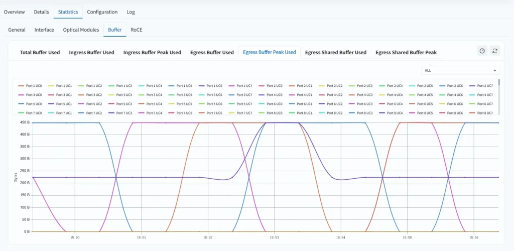
AIDC network operations platform: The platform provides visualization of PFC pause frames and per-port buffer utilization, as shown below. Operators can adjust buffer threshold policies in real time based on monitoring data, enabling data-driven performance tuning.
For configuration details, refer to Buffer Management with QoS
Conclusion: Effective Buffer Management Improves AI Network Stability
Packet buffers are critical in AI data center networks, but larger buffers are not always better. Their primary role is to absorb transient traffic bursts and provide a small reaction window—typically from hundreds of microseconds to a few milliseconds—for congestion control mechanisms such as ECN, PFC, and DCQCN to respond.
However, when buffers are too deep or when scheduling is not properly designed, packets may remain queued for too long. This leads to increased tail latency and can ultimately reduce overall training efficiency.
Therefore, when selecting AI switches, the buffer specification alone is not sufficient. Three key aspects must be considered:
- Buffer size must match the workload scenario: Large-scale AI training, RoCE networks, storage backends, and high-concurrency east-west traffic typically require deep buffers (200+ MB) to absorb microbursts. Mid-scale training clusters or inference-focused deployments can use more balanced options such as 70 MB or 48 MB. Traditional access or front-end networks usually do not require deep buffering.
- Buffer must be properly allocated: Without mechanisms such as QoS, Priority Groups (PG), queues, and buffer profiles, shared buffer resources can be consumed inefficiently. Critical training traffic may be starved of buffer space while non-critical traffic occupies excessive resources. QoS and buffer threshold policies ensure buffer resources are reserved for low-loss, low-jitter workloads.
- Congestion must be visible and adjustable: It is essential to understand whether buffers are being exhausted, whether PFC pause frames are frequently triggered, and where congestion is concentrated. The AIDC network operations platform provides visibility into per-port buffer utilization, PFC status, and congestion hotspots, enabling operators to tune configurations based on real traffic behavior.
Asterfusion AI data center switches, built on Marvell ASICs, provide multiple buffer depth options and integrate QoS, PFC, buffer profiles, and an AIDC operations platform. This enables more adaptive buffer management across different AI networking scenarios.
In summary, buffer management in AI networks is not about maximizing memory size. It is about combining the right buffer size, correct scheduling policies, and observability. Only then can networks effectively handle microbursts and high-concurrency training traffic while minimizing packet loss, controlling tail latency, and maintaining stable throughput.


