Table of Contents
As AI inference scales, network performance becomes just as important as GPU computing power. This is especially true for Prefill-Decode (PD) disaggregated inference, where separate GPU resources exchange large amounts of KV Cache data.
Traditional network designs can struggle to distribute this traffic efficiently, leading to congestion and underutilized links. Asterfusion AsterFabric Matrix takes a different approach: redesigning the network topology to deliver shorter, more predictable paths and more efficient traffic distribution.
- In DeepSeek inference testing with 64 concurrent requests, Asterfusion Matrix achieved an aggregate throughput of 13,101.82 tokens/s, representing a 21.7% improvement over AsterFabric ROFT. It also reduced Time to First Token (TTFT) by approximately 50% and Time per Output Token (TPOT) by approximately 10%, delivering higher throughput and a more responsive inference experience.
- Beyond performance, Matrix also reduces infrastructure costs. In the same 8K GPU-scale network comparison, the number of switches drops from 192 to 128—a 33% reduction in switch count. According to Asterfusion’s solution analysis, this configuration can reduce network hardware costs by approximately 30%.
- Matrix also simplifies deployment. For Dual-Plane architectures, the Asterfusion Matrix Compiler integrates GPU, NIC, NCCL, and switch configurations with the model’s performance requirements, including targets based on the theoretical Speed of Light (SOL) limit. It compiles these requirements into coordinated, network-wide configurations that can be deployed through a single operation using Zero-Touch Provisioning (ZTP), reducing manual configuration and deployment complexity.
So, how does Matrix achieve these performance gains, reduce hardware requirements, and simplify deployment? And why does its architecture matter?
1. Understanding AI Inference: Prefill, Decode, KV Cache, and PD Disaggregation
Let’s start with a simple question: How does an AI assistant like ChatGPT generate an answer when you ask it a question?
When a large language model (LLM) answers a question, the process can be divided into two main stages: Prefill and Decode.
- Prefill: This is the stage where the model processes and understands your input. When you submit a prompt, the model needs some time to process the input and calculate the information required to generate the response. This stage is called Prefill.
- Decode: Once the input has been processed, the model begins generating the answer one token at a time until the complete response is formed. This stage is called Decode.
To avoid repeatedly computing the same contextual information, the model stores intermediate data from its attention mechanism. This data is known as the Key-Value Cache, or KV Cache.
In traditional deployments, Prefill and Decode can run on the same pool of GPU resources. However, in some large-scale AI deployments, enterprises assign these two stages to different GPU servers. This approach is known as Prefill-Decode Disaggregation (PD Disaggregation).
The advantage is that enterprises can scale Prefill and Decode resources independently, allowing different GPU resources to serve different workloads more flexibly. While this approach can improve GPU resource utilization, it also introduces new networking requirements: the KV Cache generated during Prefill must be transferred efficiently to the Decode resources.
Think of it as a busy logistics center: one team handles packaging, while another handles delivery. A large volume of packages must move between the two teams. If the roads connecting them are poorly designed, simply adding more workers will not fundamentally solve the traffic congestion.
AI inference faces a similar challenge. GPUs may be ready to perform computations, but if the network cannot efficiently deliver the required data, GPU computing efficiency can suffer.
2. Why Traditional Network Architectures Become Bottlenecks in PD Disaggregation
Traditional large-scale AI clusters commonly use symmetric topologies such as Clos/Fat-Tree and ROFT. These architectures were originally designed to support symmetric collective communication patterns in AI training, such as All-Reduce and All-to-All. However, when directly applied to PD-disaggregated inference, they can expose several challenges, including hash polarization, structural congestion, high tail-latency variation, and high hardware costs.
Hash Polarization: Uneven Traffic Distribution. ECMP distributes traffic by hashing individual flows. Multiple high-volume KV Cache transfers may be assigned to the same link, causing some links to become congested while others remain underutilized, ultimately increasing inference latency.
Structural Congestion: A Mismatch Between Network Architecture and Inference Traffic. ROFT’s rail optimization is primarily designed for training workloads, whereas the direction of KV Cache transfers in PD-disaggregated inference is dynamically determined by the scheduler. This can concentrate traffic on the uplinks of certain Leaf switches, creating persistent network hotspots.
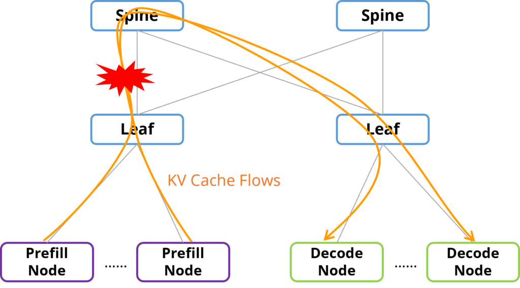
Multi-Hop Forwarding and Spine Bottlenecks: Longer Paths and Concentrated Traffic. In traditional three-tier Clos networks, communication between different Leaf switches must pass through the Spine layer. In PD-disaggregated inference, large volumes of KV Cache traffic need to travel between different Leaf switches, making the Spine layer a potential traffic aggregation point and increasing network latency and the risk of congestion.
3. The Core Idea Behind Asterfusion Matrix: Eliminating the Spine Layer
Asterfusion AsterFabric Matrix addresses these challenges by redesigning the network topology itself, rather than relying solely on workload scheduling or more complex transport-layer protocols.
3.1 Its architecture is built around four key principles:
- Remove the Spine layer: Eliminate the traditional Spine-layer aggregation point for cross-Leaf traffic and reduce the forwarding path from three switch hops to two.
- Build a complete bipartite mesh: Divide Leaf switches into two groups and fully interconnect the two groups, providing direct and predictable paths for KV Cache transfers.
- Combine single-rail and multi-rail access: Use different server access patterns to distribute GPU traffic across Leaf switches and reduce structural hotspots.
- Enable deterministic routing: Provide a defined, optimal two-switch-hop path between GPU endpoints, reducing dependence on ECMP hash-based path selection.
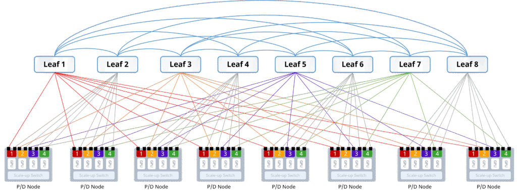
Matrix is not simply an attempt to optimize individual links. It redesigns the network structure to reduce potential aggregation bottlenecks at their source.
3.2 Network Topology
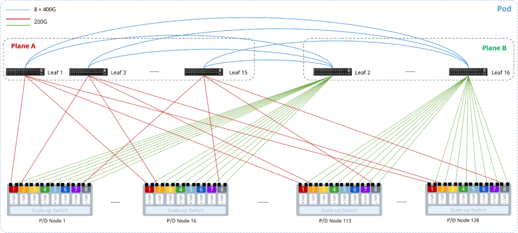
The Matrix architecture removes the Spine layer from the traditional Fat-Tree topology and divides all Leaf switches into two equal-sized groups:
- Plane A (Multi-Rail Plane, odd-numbered Leaf switches): Numbered 1, 3, 5, …
- Plane B (Single-Rail Plane, even-numbered Leaf switches): Numbered 2, 4, 6, …
The two groups of switches form a complete bipartite mesh. Every switch in Group A has a direct link to every switch in Group B, while switches within the same plane are not interconnected.
Each GPU server uses a dual-port NIC, with the two ports connected to the two switch groups respectively:
- Port 1 (Multi-Rail Port): Connects to odd-numbered Leaf switches in Plane A according to multi-rail rules.
- Port 2 (Single-Rail Port): Connects to even-numbered Leaf switches in Plane B according to single-rail rules.
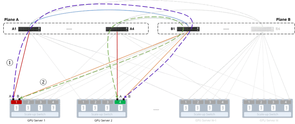
The following diagram illustrates a minimum deployment consisting of four GPU servers and four Leaf switches in each plane.
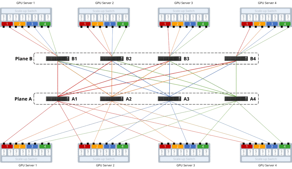
Each server’s multi-rail port connects to the four Leaf switches in Plane A, while its single-rail port connects to the four Leaf switches in Plane B. The two groups of Leaf switches are fully interconnected.
With this topology, the forwarding path between any two GPUs across different servers consists of two switch hops:GPU → Leaf in the source plane → Leaf in the opposite plane → GPU
In PD-disaggregated inference scenarios, this means that KV Cache transfers between any Prefill node and any Decode node traverse only two switches, providing a shortest and deterministic forwarding path.
3.3 Traffic Paths
The forwarding paths between GPUs under different communication scenarios are described below.
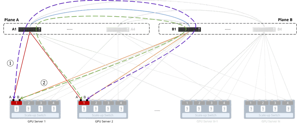
Same-Rail Communication
When GPU 1 on Server 1 communicates with GPU 1 on Server 2, the traffic can follow either of the following paths:
- Server 1-1-A → Leaf A1 → Leaf B1 → Server 2-1-B, completing forwarding in two switch hops.
- Server 1-1-B → Leaf B1 → Leaf A1 → Server 2-1-A, completing forwarding in two switch hops.
Cross-Rail Communication
When GPU 1 on Server 1 communicates with GPU 4 on Server 2, the traffic can follow either of the following paths:
- Server 1-1-A → Leaf A1 → Leaf B1 → Server 2-4-B, completing forwarding in two switch hops.
- Server 1-1-B → Leaf B1 → Leaf A4 → Server 2-4-A, completing forwarding in two switch hops.
4. What Performance Gains Does Matrix Deliver?
The true value of any network architecture must ultimately be proven in real-world workloads.
4.1 Uncompromised Baseline Performance with Higher Optimization Headroom
In single-flow forwarding and standard collective communication benchmarks, Matrix matches the performance of mainstream ROFT (All-Reduce: 153.01 GB/s vs. 152.93 GB/s; All-to-All: 29.69 GB/s vs. 29.67 GB/s).
Following parameter tuning, Matrix’s All-Reduce bus bandwidth scales further to 162.78 GB/s, while All-to-All reaches 30.11 GB/s.
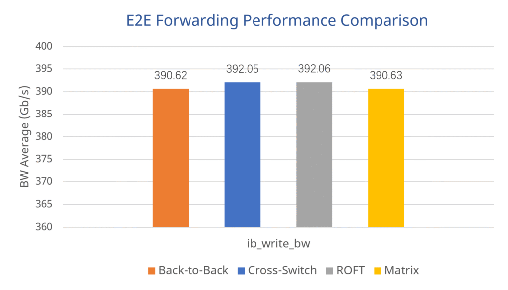
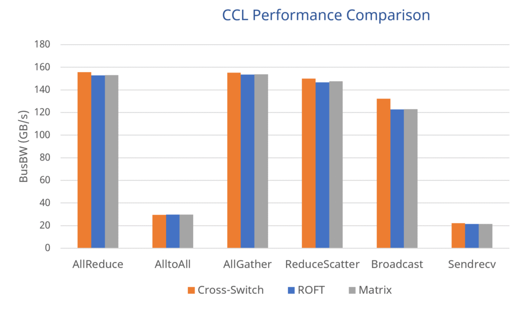
This clearly demonstrates that a spine-less topology still provides a rock-solid, high-performance communication foundation.
4.2 In Real-World Inference: Faster First-Token Response, Smoother Token Generation, and Higher Throughput
Asterfusion’s Matrix test report evaluates AsterFabric Matrix against AsterFabric ROFT under a DeepSeek-V4-Flash inference workload using a 2 Prefill / 2 Decode (2P2D) node deployment.
The benchmark results show that Matrix achieves notable improvements across total throughput, Time to First Token (TTFT), and Time per Output Token (TPOT):
- Higher Concurrent Throughput: Under a high concurrency of 64 requests, the cluster’s aggregate throughput hits 13,101.82 tokens/s—a significant 21.7% increase over ROFT.
- Faster First-Token Response: The user-facing Time to First Token (TTFT) drops dramatically from 2,403.08 ms to 1,215.97 ms (a ~50% reduction), effectively eliminating perceived latency lag.
- Smoother Generation Flow: Time per Output Token (TPOT) decreases by approximately 10% (from 19.14 ms down to 17.34 ms).
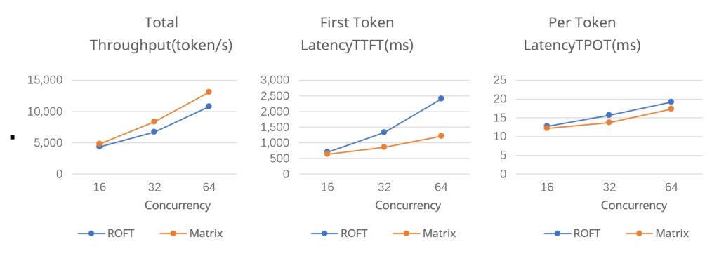
| Concurrency | Total Throughput (token/s) | TTFT(ms) | TPOT(ms) | |||
| ROFT | Matrix | ROFT | Matrix | ROFT | Matrix | |
| 16 | 4,366.97 | 4,825.18 | 702.5 | 628.72 | 12.77 | 12.13 |
| 32 | 6,714.27 | 8,369.02 | 1,327.98 | 853.88 | 15.69 | 13.66 |
| 64 | 10,765.62 | 13,101.82 | 2,403.08 | 1,215.97 | 19.14 | 17.34 |
- TTFT (Time to First Token): The time elapsed between submitting a request and receiving the first generated token. Lower is better.
- TPOT (Time per Output Token): The average time required to generate each subsequent output token, depending on the measurement methodology used in the test. Lower is better.
These results are consistent with Matrix’s design goals: improving communication efficiency between inference resources and reducing the impact of networking on overall inference performance. These improvements are particularly important for inference services handling large numbers of concurrent requests. Higher aggregate throughput means more output tokens can be generated per unit of time, while lower TTFT and TPOT help improve response times and the overall streaming generation experience.
5. Another Key Advantage: Fewer Switches, 30% Lower Network Hardware Costs
Performance is not the only factor to consider when building an AI network. As GPU clusters scale, the number of switches, optical transceivers, and cables can become a significant part of the overall infrastructure cost. Asterfusion compared three network configurations at the same 8K GPU scale: AsterFabric ROFT, AsterFabric Dual-Mesh, and AsterFabric Matrix.
Network Hardware Comparison Across Architectures for an 8K-GPU Cluster
| Component | AsterFabric ROFT | AsterFabric Dual-Mesh | AsterFabric Matrix |
|---|---|---|---|
| Switches | 192 | 192 | 128 |
| 800G Optical Transceivers | 12,288 | 12,288 | 8,192 |
| 400G Optical Transceivers | 8,192 | — | — |
| 200G Optical Transceivers | — | 16,384 | 16,384 |
| Cables | 12,288 | 12,288 | 10,240 |
Source: Asterfusion, AsterFabric Matrix Inference Network Solution, Version 1.1. The figures represent the network configurations compared in the solution document.
The number of switches drops from 192 to 128. This means that, at the same 8K GPU scale, Matrix eliminates 64 switches, reducing the total switch count by approximately 33%.
Compared with the ROFT configuration, Matrix uses fewer 800G optical transceivers. It also requires fewer cables than either of the other two configurations.
According to the configuration cost analysis in the solution document, Matrix can reduce network hardware costs by approximately 30%–40% in the specific 8K GPU deployment compared. The test report also indicates that Matrix can reduce network hardware costs and overall power consumption by approximately 30%.
These figures apply to the specific configurations evaluated in the solution document and test report. Actual savings in a production deployment will depend on the selected hardware, optical transceivers, cabling, and specific deployment requirements.
The overall direction, however, is clear: Matrix aims not only to improve network traffic efficiency but also to reduce the networking infrastructure required to support a GPU cluster of the same scale.
6. Scaling from a Single Pod to 16K GPUs
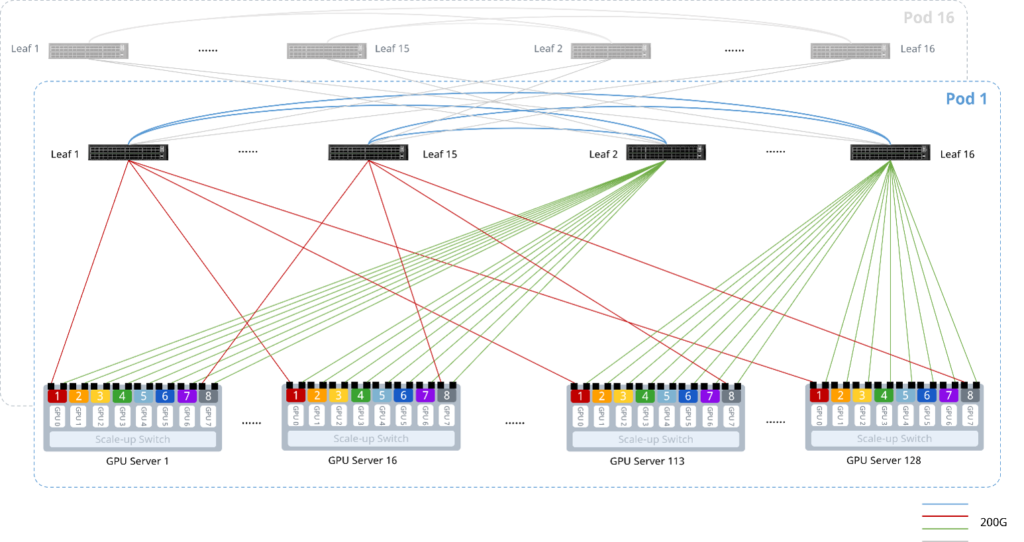
Matrix is designed to support more than just small-scale inference clusters. The solution uses 51.2 Tbps switch platforms, with 400 Gbps of network bandwidth per GPU server.

A single Matrix Pod can support up to 128 GPU servers. With eight GPUs per server, this corresponds to approximately 1K GPUs per Pod.
The architecture can scale to a maximum of 16 Pods, supporting deployments of approximately 16K GPUs. This provides a path for scaling AI inference infrastructure from a single Pod to much larger deployments while retaining the same core design principles: two Leaf planes, direct interconnection between planes, structured dual-rail connectivity, and controlled host-route advertisement.
For infrastructure teams, this means the same core architectural principles can be applied across deployments of different sizes, while the number of switches and port configurations can be planned according to actual scale requirements.
7. Engineering for Deployment: Seamless, Standardized Scaling from 1K to 16K GPUs
Even the most advanced topology innovations must ultimately prove themselves in real-world deployment. From the outset, AsterFabric Matrix has been designed around two core objectives: simplified deployment and seamless scaling.
Intelligent Compilation and ZTP: Automated Network Bring-Up in Seconds
For Dual-Plane networks, Asterfusion’s proprietary AsterFabric Matrix Compiler integrates the stringent requirements of AI workloads, including performance targets approaching the theoretical Speed of Light (SOL) limit. It combines the heterogeneous parameters required by GPUs, NICs, NCCL, and switches, intelligently compiling them into a consistent, deterministic configuration that can be deployed across the entire network with a single action. Through Zero-Touch Provisioning (ZTP), the entire network can be deployed automatically, eliminating the need for extensive manual configuration and troubleshooting.
Unified Hardware Platform: Simplified Spare Parts and Maintenance
The entire network uses a standardized hardware platform: Asterfusion’s CX864E-N ultra-low-latency 800G data center switch, with forwarding latency as low as 560 ns per switch.
With the Spine layer eliminated, Leaf switches handle both server access and interconnection. This allows a single Pod to use a uniform switch model, simplifying maintenance and spare-parts management while eliminating the complexity of maintaining different hardware platforms across network layers.
Automatic IPv6 Peering: Less Manual Network Planning
The A and B planes use IPv6 Link-Local addresses to establish unnumbered BGP peering. Individual interface IP addresses do not need to be planned and assigned separately.
Combined with automatic host-route advertisement through ARP-to-Host, this approach significantly reduces network configuration effort and deployment time.
Standardized Pod Architecture: Flexible Scaling Across Deployment Sizes
Matrix follows a strict 1:1 non-blocking oversubscription ratio, enabling seamless scaling from smaller edge clusters with hundreds of GPUs to large-scale inference infrastructure supporting tens of thousands of GPUs.
- Standard 1K GPU Pod: Just 16 CX864E-N switches—eight in each of the A and B planes—can support 128 eight-GPU compute nodes, delivering full line-rate forwarding over a two-hop network path.
- Large-Scale 8K–16K GPU Clusters: By replicating standardized Pods, Matrix can scale to support up to 16,384 interconnected GPUs, providing predictable, on-demand expansion for large-scale AI inference clusters.
Conclusion
AI inference networking is not just about port counts or total bandwidth. The network topology must also match how GPUs communicate. For PD-disaggregated inference, large KV Cache transfers between Prefill and Decode can create traffic imbalances and congestion. Asterfusion AsterFabric Matrix addresses this challenge with a Spine-free, dual-plane architecture designed to deliver shorter, more predictable paths and more efficient traffic distribution.
Test results show the potential benefits: higher DeepSeek inference throughput, lower TTFT and TPOT, and fewer switches in the 8K GPU configuration comparison.
Rather than treating congestion as a problem to fix after it occurs, Matrix aims to reduce structural bottlenecks through network design from the outset.
Read the test report below for more details on the architecture and performance results.
For more:
What Is Prefill-Decode Disaggregation And How To Cut CAPEX For AI Inference Fabrics By Around 30%
KV Cache in LLM Inference: From Memory Bottleneck to Network Architecture Optimization
AI Training Network Architecture: Asterfusion Dual-Mesh Fabric Design
AI GPU Backend Network Design: Rail-Only And Rail-Optimized Architectures
AsterFabric Matrix: Network Architecture For PD-Disaggregated In AI Inference


