With the increased use of new technologies like the Internet of Things(IoT), artificial intelligence (AI), and machine learning (ML),etc,it can be predicted that in the next two or three decades, we will enter a smart society based on the Internet of Everything(IoE). Now,the computing power of the data center becomes the new productivity. In order to best meet the needs of customers in a digital world, it must be able to process large amounts of data faster than standard computers. Thus,High-performance computing (HPC) solutions are being favored by enterprises.
Understanding High Performance Computing/HPC
What is HPC (High-Performance Computing)
High-performance computing is the capability of processing data and performing complex calculations at extremely high speeds. For example, a laptop or desktop computer with a 3 GHz processor can perform about 3 billion calculations per second, which is much faster than any human being can achieves, but it still pales in comparison to HPC solutions that can perform trillions of calculations per second. The general architecture of HPC is mainly composed of computing, storage, and network. The reason why HPC can improve the computing speed is that it adopts “parallel technology”, using multiple computers to work together, using ten, hundreds, or even thousands of computers, which enables them “working in parallel”. Each computer needs to communicate with each other and process tasks cooperatively, which requires a high-speed network with strict requirements on latency and bandwidth.
Key Factors of HPC Performance
Processor performance: This refers to the central processing unit (CPU) or graphics processing unit (GPU)’s processing power. To increase processing power, HPC systems often use multiple processors working in tandem.
Memory performance: HPC systems require a large amount of memory (RAM) to support complex computations and large data sets. This factor refers to the speed and capacity of the system memory.
I/O Performance: The speed at which data is imported and exported from storage devices is critical to the performance of an HPC system. To support fast processing of large data sets, high-speed storage devices are necessary.
Network Performance: HPC systems rely on a high-speed network to connect their various components and support communication between multiple processors and storage devices. This factor refers to the speed and capacity of the network.
Application scenarios of High-performance computing (HPC)
High-performance computing (HPC) demands diverse network performance levels based on various application scenarios. These scenarios can be broadly categorized into three distinct types:
Loosely Coupled Computing Scenario: Here, computing nodes operate with minimal dependence on each other’s information, resulting in lower network performance requirements. Examples include financial risk assessment, remote sensing and mapping, and molecular dynamics. This scenario imposes relatively low demands on the network.
Tightly Coupled Scenario: This type features high interdependence among computing nodes, necessitating synchronized calculations and rapid information exchange. Typical applications are electromagnetic simulations, fluid dynamics, and car crash simulations. Such scenarios require networks optimized for extremelylow latency.
Data-Intensive Computing Scenario: Characterized by the need to handle massive amounts of data and generate significant intermediate datasets during processing. Examples include weather forecasting, gene sequencing, graphics rendering, and energy exploration. High-throughput networks are essential here, along with moderate low-latency capabilities.
In summary, HPC scenarios emphasize two critical network attributes: High bandwidth and low latency As a result, RDMA is generally used to replace TCP protocol to reduce latency and server CPU occupancy.
Why RDMA in HPC? Understanding RDMA
Why RDMA in HPC?
Before RDMA technology emerged, traditional data centers relied heavily on the Ethernet TCP/IP protocol stack for data transmission. However, as high-performance computing demands grew, TCP/IP network communication became less suitable. The main drawbacks are:
When handling messages with the TCP protocol stack, the kernel must perform multiple context switches, each taking around 5-10 microseconds, along with at least three data copies and CPU-dependent protocol encapsulations. This contributes to a fixed delay of several tens of microseconds purely for protocol stack processing, creating a major bottleneck in systems requiring microsecond-level performance, such as AI-driven data computations and SSD distributed storage.
Drawback 2: TCP/IP protocol stack processing leads to high CPU usage
Besides the long latency issue, the TCP/IP network demands that the host CPU partakes in several rounds of protocol stack memory copying. As network size and bandwidth increase, this places a significant scheduling burden on the CPU during data transmissions, leading to consistently high CPU load.
In order to achieve high throughput and low latency, the industry generally adopts RDMA (Remote Direct Memory Access) to replace the TCP protocol, to achieve a reduction in latency and reduce the occupancy of the server CPU.
What is RDMA(Remote Direct Memory Access)
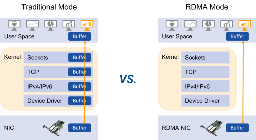
RDMA (Remote Direct Memory Access) is developed to solve the delay of server-side data processing in network transmission. It can directly access the memory of one host or server from the memory of another host or server without using the CPU. It frees up the CPU to do what it’s supposed to do, such as running applications and processing large amounts of data. This both increases bandwidth and reduces latency, jitter, and CPU consumption.
RDMA excels with its kernel bypass mechanism, which facilitates direct data exchange between applications and network cards, sidestepping TCP/IP limitations and cutting protocol stack latency down to almost 1 microsecond. Additionally, RDMA’s zero-copy memory mechanism eliminates the need to shuffle data between application memory and OS buffers. This means transmission doesn’t engage the CPU, cache, or context switches, significantly slashing processing delays in message transfer. Moreover, this transmission happens concurrently with other system operations, boosting network performance.
However, RDMA is highly sensitive to packet loss. Unlike the well-known TCP protocol that retransmits lost packets with precision—removing received messages to avoid redundancy while only resending what’s lost—the RDMA protocol retransmits all messages in a batch when a single packet is lost. Therefore, RDMA can handle full-rate transmissions flawlessly in a lossless environment, but its performance plummets sharply upon packet loss. A packet loss rate above 0.001 can drastically reduce effective network throughput, and at a rate of 0.01, it drops to zero. For optimal RDMA performance, the packet loss rate must stay below 1e-05 (one in 100,000), ideally achieving zero packet loss. This makes achieving a lossless state crucial for ROCE networks.
The most important technology on ROCE –ECN/PFC
ECN (Exploration Congress Notification) is an important means of building a lossless Ethernet that provides end-to-end flow control. Using the ECN feature, once congestion is detected, the network device marks the ECN domain at the IP head of the packet. When ECN-marked packets arrive at their intended destination, congestion notifications are fed back to the traffic sending side. The traffic sender then responds to the congestion notification by limiting the rate of the problematic network packets, thus reducing network latency and jitter of high performance computing clusters.
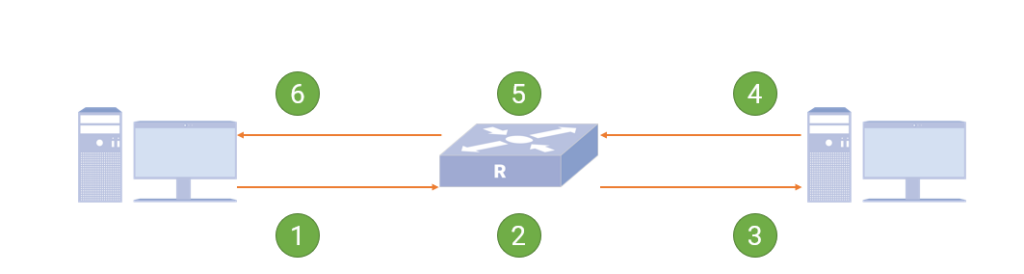
How ECN works ?
The sending server sends an IP message with an ECN mark.
The switch receives the message when the queue is congested, modifies the message ECN field and forwards it.
The receiving server receives the marked congestion message and processes it normally.
The receiving end generates a congestion notification and periodically sends a CNP (Congestion Notification Packets) message, requiring that the message cannot be discarded by the network.
After receiving the CNP message, the switch forwards the message normally.
The sending server receives the marked CNP message, parses it, and uses the corresponding data flow rate limit algorithm to limit the rate.
Provides lossless networking using Priority Flow Control (PFC )
As an enhancement of the pause mechanism, Priority Flow Control (PFC) allows 8 virtual channels to be created on an Ethernet link, assigning a priority level to each virtual channel and allocate dedicated resources (such as cache, queue, etc.), allowing individual to suspend and restart any one of the virtual channels without affecting other virtual channels’ traffic transmission .This approach enables the network to create a lossless service for a single virtual link and to coexist with other traffic types on the same interface.
How does PFC work?
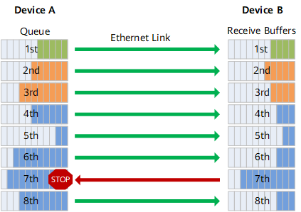
As shown in the figure, the sending interface of Device A is divided into 8 priority queues, and the receiving interface of Device B has 8 receiving buffers, which correspond to each other. When a receiving buffer on the receiving interface of Device B is congested, a back pressure signal “STOP” is sent to Device A, and Device A stops sending traffic in the corresponding priority queue.
It can be seen that PFC solves the conflict between the existing Ethernet Pause mechanism and link sharing. The flow control is only for one or several priority queues, rather than interrupting the traffic of the entire interface. Each queue can pause or restart traffic sending separately without affecting other queues, truly realizing multiple traffic sharing links.
ECN vs PFC advantages
The advantages of ECN/PFC can be seen when compared to the old or basic congestion handling mechanism. Unlike the mechanism that discards messages when congestion is detected, ECN handles congestion without actively discarding messages. This approach offers several benefits:
Enhanced transmission performance: The old mechanism of discarding messages leads to unnecessary efficiency waste. In contrast, ECN and PFC notify the transmission end to adjust the transmission speed when congestion is detected. This effectively improves the transmission efficiency.
Reduction of head-of-line (HOL) blocking: Many network transport protocols rely on processing messages in a specific order. In cases where a fragment of a single message is discarded due to congestion, it results in HOL blocking, where the receiving end waits for the transmitting end to re-deliver the discarded fragment. By implementing ECN and PFC technology, the occurrence of HOL blocking can be significantly reduced.
Decreased probability of Retransmission Timeout (RTO): When a packet is missed or discarded, the transmission protocol initiates the retransmission mechanism. Consequently, as the probability of discarding increases, the number of retransmissions also increases, hampering transmission efficiency. PFC, unlike IEEE 802.3x‘s flow control, allows for the adjustment of speed within specific port queues, offering greater flexibility in application services. Additionally, PFC incorporates a watchdog mechanism that can choose to discard or forward packets during continuous congestion occurrences.
ECN vs PFC Technical Comparison
Comparison items
PFC
ECN
Network location
Layer 2
Network layer & transport layer
Scope of application
Point to point
End-to-end
Whether full network support is required
Yes
NO
Controlled objects
The previous node in the network, if the server network card supports PFC, PFC can also take effect on the network card
Sending host
Message cache location
Intermediate network node and sender
Sender
Affected traffic
All traffic in one of the 8 forwarding queues in the network device
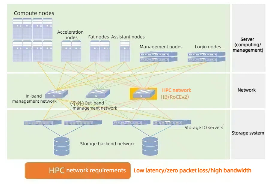
HPC high-performance computing is a network deployment scenario that integrates the computing power of multiple units.
In this scenario, four networks need to be deployed for effective performance:
High-performance computing network: this network carries HPC server co-computing traffic and provides access to distributed storage traffic. The high-performance computing network requires ultra-high performance, low-latency, high-efficiency, stable, and reliable connection characteristics. To achieve this, it is necessary to deploy an RDMA high-performance lossless network.
Storage network: This network is responsible for the traffic between the storage nodes. Its purpose is to ensure quick and non-blocking multi-copy synchronization, post-failure data reconstruction, and other tasks within the distributed storage cluster. Deploying an RDMA high-performance lossless network is essential for optimal performance.
In-band management network: This network is used to collect cluster status information and enable management functions such as remote login.
Out-of-band management network: This network is utilized for out-of-band monitoring and management functions.
Once the basic connection and configuration are completed, it is important to prioritize the traffic of the entire network according to the business scenario. Enabling Priority Flow Control (PFC) for all switches ensures that different types of business traffic enter different queues for forwarding. By doing so, HPC high-performance business traffic based on RoCEv2 can be given priority. Additionally, enabling Explicit Congestion Notification (ECN) on all switches helps to maintain low latency and high throughput for high-performance computing queues. It should be noted that the switch and server network card parameters need to be consistent, and configurations such as queue division, cache, PFC threshold, and ECN threshold should be dynamically adjusted based on the business situation to achieve optimal performance.
Asterfusion CX-N low latency ROCE switches in HPC Scenario
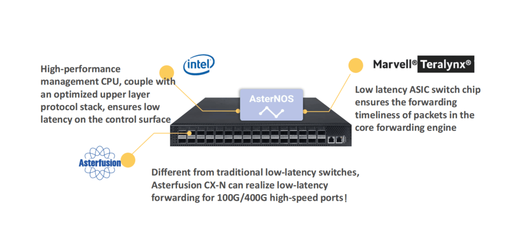
Based on the understanding of high-performance computing network requirements and RDMA technology, Asterfusion launched the CX-N series of ultra-low latency cloud switches. It uses a fully open, high-performance network hardware + transparent SONiC -based open network system (AsterNOS), to build a low latency, zero packet loss, high-performance Ethernet network for HPC scenarios, which not bound by any vendor.
Extremely cost-effective, CX-N switches have port to port minimum 400ns forwarding delay,the forwarding delay is the same at full rate (10G~400G);
Supports RoCEv2 to reduce the delay of transmission protocol;
Support PFC, ECN, DCTCP,etc. to deliver low-latency, zero packet loss, non-blocking Ethernet;
HPC networking design based on Asterfusion CX-N ROCE Switch
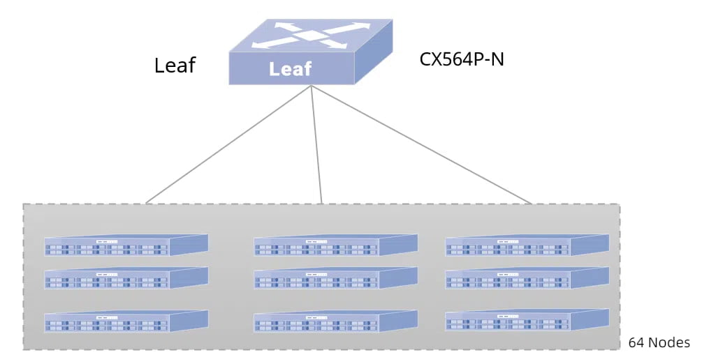
HPC single-layer network
Take the construction of a HPC high-performance computing network with 64 servers as an example: Spine and Leaf are fully interconnected using 100GE links, and the server uses a 100GE network card to access the Leaf switch, and the network card needs to support the RoCEv2 protocol. When the number of server nodes is less than or equal to 64 nodes, it is recommended to use a single-layer network, and the Leaf switch uses the CX564P-N that supports 64*100GE ports.
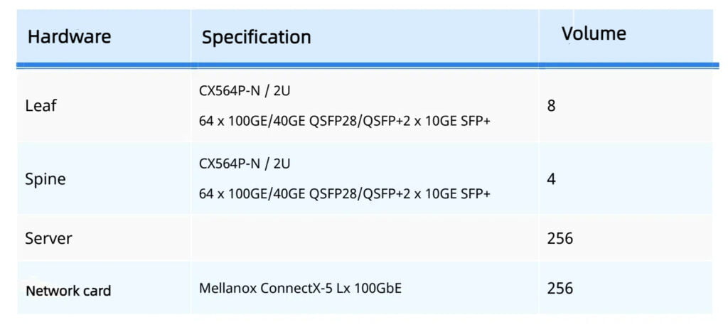
HPC 2-Tier Architecture
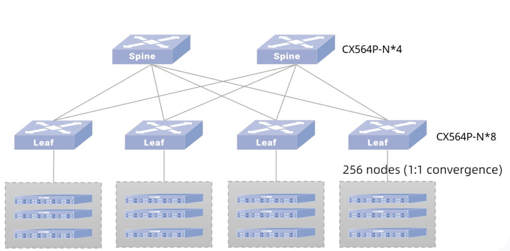
Take the construction of an HPC high-performance computing network with 256 servers as an example: Spine and Leaf are fully interconnected using 100GE links, and the server uses a 100GE network card to access the Leaf switch, and the network card needs to support the RoCEv2 protocol. The switch selection is shown in the right table.
When the number of server nodes is larger than 64 nodes, it’s recommended to adopt two-tier networking, and the Spine and Leaf switches adopt CX564P-N which supports 64 *100GE ports. Network convergence ratio of 1:1, network architecture as shown in the left figure.
Test Data of Asterfusion Ultra Low Latency Switch vs. InfiniBand Switch on HPC scenorio
01 Lab Test
This test was conducted on the network built by CX-N ultra-low latency cloud switch (CX-N for short) and Mellanox MSB7800 (IB for short) switch.
Test 1: E2E forwarding
Test E2E (End to End) forwarding latency and bandwidth of the two switches under the same topology.
This scheme uses Mellanox IB packet delivery tool to send packets, and the test process traverses 2~8388608 bytes.
The CX-N switch has a bandwidth of 92.25Gb/s and a single delay of 480ns.
The bandwidth of the IB switch is 96.58Gb/s, and the delay of a single unit is 150ns.
In addition, the CX-N ‘s delay fluctuation of traversing all bytes is smaller, and the test data is stable at about 0.1us.
Comparing Asterfusion CX-N low latency switch and Mellanox IB , the CX-N is more cost-effective.
Table 1: Comparison of AsterfuionCX-N vs IB forwarding delay data
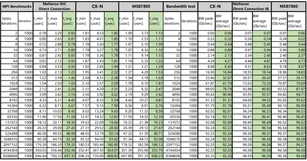
Test 2 (MPI benchmark)
MPI benchmarks are commonly used to evaluate high performance computing ‘s performance.
OSU Micro-Benchmarks are used to evaluate the performance of Asterfusion CX-N and IB switches.
The CX-N switch has a bandwidth of 92.63Gb/s and a single delay of 480ns.
The bandwidth of the IB switch is 96.84Gb/s, and the delay of a single unit is 150ns.
Table 2: Comparison of CX-N vs IB MPI test data
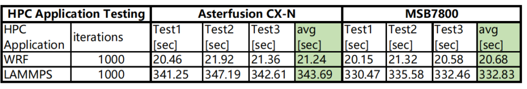
Test 3: HPC Applications
Run the same tasks in each HPC application and compare the speed of the CX-N and IB switches. Conclusion: The operating speed of CX-N switches is only about 3% lower than that of IB switches.
Table 3: Comparison of CX-N vs IB HPC application test
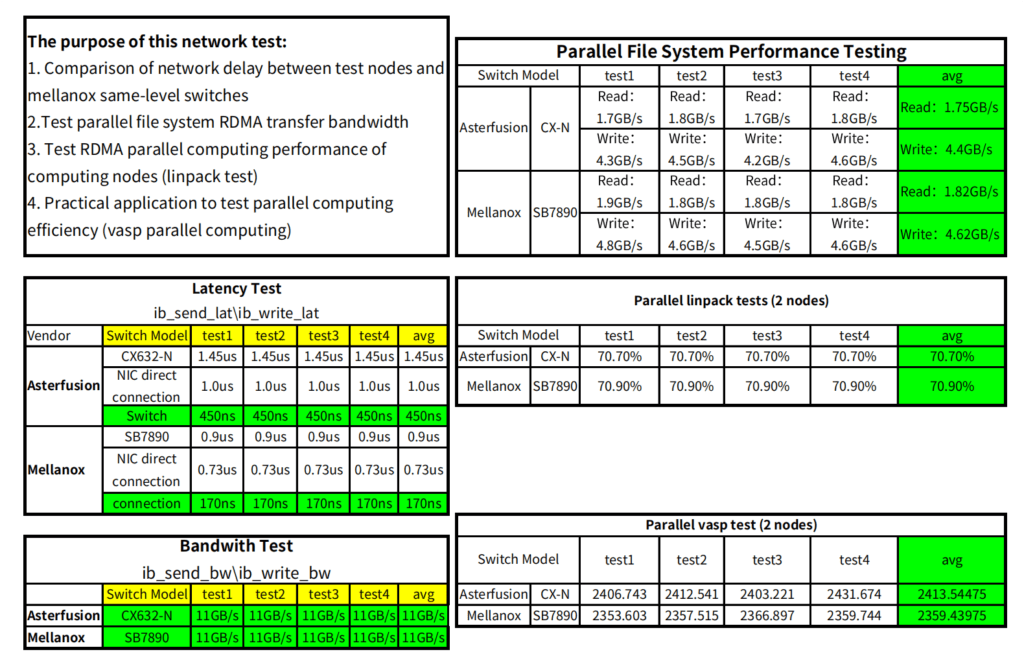
02 Comparison of customer field test data
It is basically consistent with the results obtained in the lab, and even better.
How to quick configure ROCEv2 on Asterfusion SONiC data center switch
Conclusion:
Asterfusion CX-N low latency switches utilize ROCE to deliver the performance of IB switches at a significantly lower price, making it an affordable for HPC scenarios.
When enterprise users have a limited budget, but at the same time have a high demand for latency in HPC scenarios, which can choose Asterfusion Teralynx based CX-N low latency switches as a chioce. It offers a truly low-latency, zero-packet-loss, high-performance, and cost-effective network for high-performance computing clusters.
For more information about Asterfusion CX-N low latency ROCE switch, please contact bd@cloudswit.ch