Table of Contents
PTP (Precision Time Protocol) is a protocol for clock synchronization in networks. When supported by hardware, PTP is able to achieve sub-microsecond accuracy, which is much higher than NTP. So PTP is widely used in scenarios that require high-precision clock synchronization, such as audio/video synchronization, Fintec, and industrial automation.
For the basic concepts of PTP, see this blog: https://cloudswit.ch/blogs/what-is-ptp-and-how-does-it-work/
Recently, we did some testing between the most common PTP implementations available today, Linux PTP, and the enterprise SONiC (AsterNOS) provided by Asterfusion. Hope this article will be informative for you in choosing a PTP implementation solution!
What is Linux PTP
In Linux, the implementation of the PTP protocol is called Linux PTP, which is based on the IEEE 1588 standard, the package includes ptp4l and phc2sys.
Ptp4l implements PTP boundary clocks and common clocks, and supports hardware and software time synchronization.
- Hardware time stamps are used to synchronize the PTP hardware clock with the master clock
- Software time stamps are used to synchronize the system clock with the master clock.
Phc2sys is used to synchronize the system clock to the PTP hardware clock (PHC) on the NIC.
More details can be found at: https://sourceforge.net/projects/linuxptp/
LinuxPTP Architecture
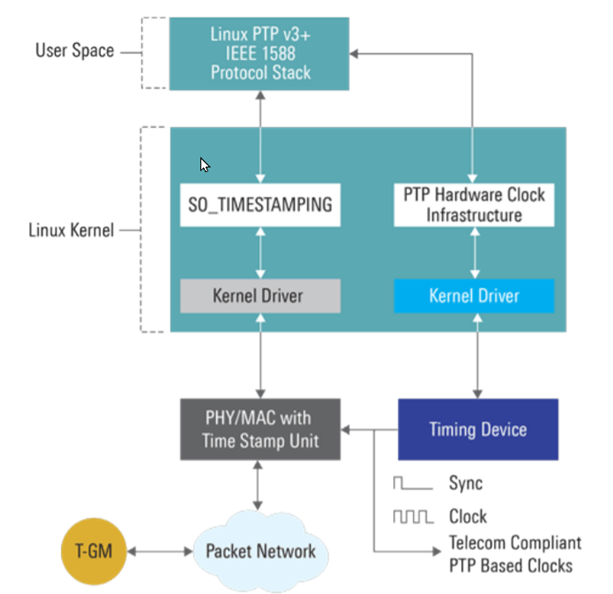
The linuxPTP architecture is divided into two parts: kernel space and user space. There are two hardware drivers, one is the PHY/MAC with an internal TSU localtime stamp unit, and the other is the PTP Hardware Clock with an internal counter called TOD (Time of Day). In order to use PTP, the kernel driver must support either software or hardware time stamping, as does the NIC.
Test result of Linux PTP(ptp4l) + Linux NIC
Here we did a test based on ptp4l and the Linux NIC, you can see: the synchronization accuracy is distributed within 1000ns(1μs), but there are unstable jumps with more than 8000ns(8μs).
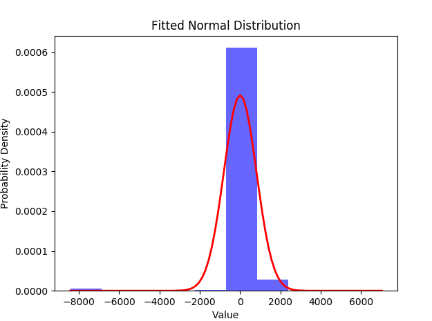
Without additional software tuning, it may be sufficient for personal experiments with certain requirements on time precision. However, in more demanding commercial scenarios and larger-scale PTP domains, we need to further optimize the PTP performance to meet the needs of services such as intelligent driving, 5G, industrial automation, etc.
What are PTP-optimized SONiC Switches?
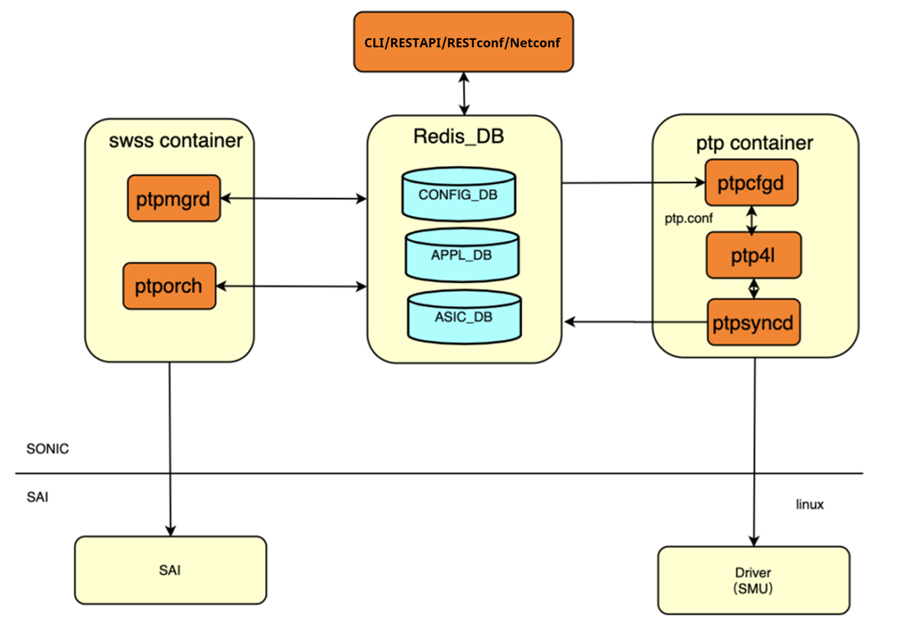
SONiC system’s architecture comprises of various modules that interact among each other through a centralized and scalable infrastructure.
Asterfusion leads the community in implementing PTP in SONiC and optimizing its performance on the Enterprise SONiC Distribution–AsterNOS. Here we show the PTP subsystems, and there is a ptp container that runs Linux PTP /ptp4l and interacts with RedistDB and hardware drivers. Additionally, it is compatible with multiple network management protocols such as RESTful API, RESTconf, Netconf for easy integration and better interoperability.
AsterNOS virtualization images for network simulators, please visit:
https://www.gns3.com/marketplace/appliances/asterfusion-vasternos
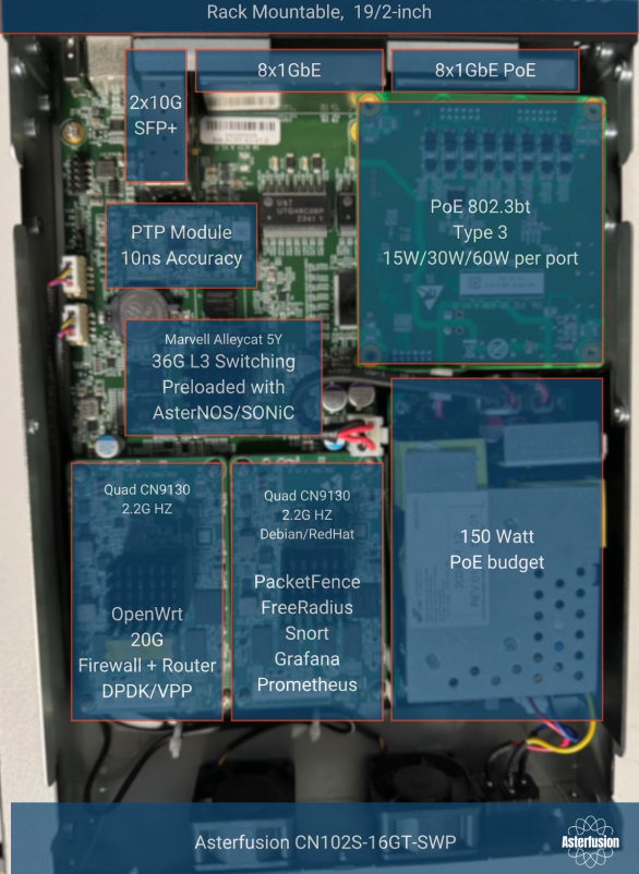
In the hardware side, this white box switch integrates a PTP module to help with IEEE1588 and Synchronous Ethernet (SyncE), and it is removable (such as the PoE switch shown below, and yes, it even has 2 built-in DPU modules). Additionally, all ports support PTP and this switch can be used as both Boundary Clock (BC) and Transparent Clock (TC).
Time offset test on PTP-optimized SONiC switches
Before testing, let’s quickly review how PTP is implemented and the key terms involved.
2 Synchronization Mechanism in PTP switches: One-step and two-step
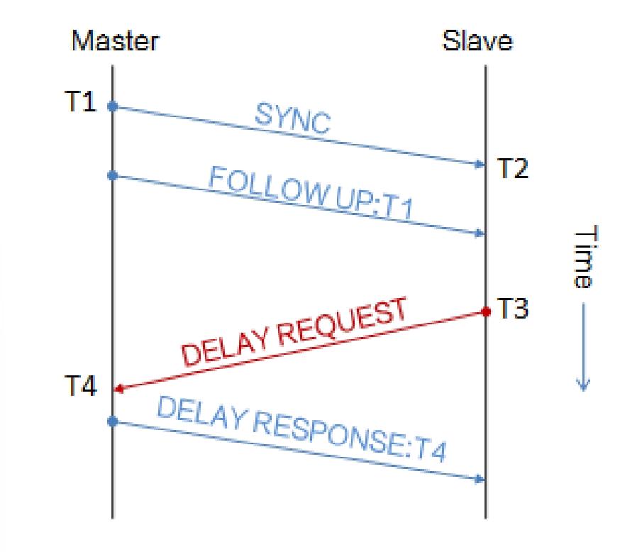
The time offset and transmission delay are calculated from the clock based on T1, T2, T3, T4
The one-step clock uses Sync and Pdelay Resp to carry timestamp information without sending Follow-up. It interacts with fewer messages than the two-step mode and consumes less network bandwidth, but the timestamps sent are the estimated time of message delivery, which is not as accurate as the two-step mode.
The two-step clock uses Follow-up to carry the timestamp, and the timestamp sent is the actual sending time, which can improve the accuracy of PTP time synchronization. However, if you’re just buying PTP-enabled switches to integrate into your network, these are less important and it’s okay to mix the two modes.
PTP Delay Measurement Mechanism: E2E or P2P
The measurement mode used by all clock nodes within a PTP domain must be the same. If there is no transparent clock(TC) in the network (works by updating PTP messages to correct for time spent in the device), there is little difference. We need to choose between E2E TC or P2P TC according to the actual networking needs.
In E2E mechanism, the TC sends sync messages all the way through the network. In P2P, each device on the network exchanges peer-delay measurement messages. TC responds to the sync messages and then sends its own Sync message to the OC, and OC can add up all of the path delay and the residence time to come up with the total network delay.
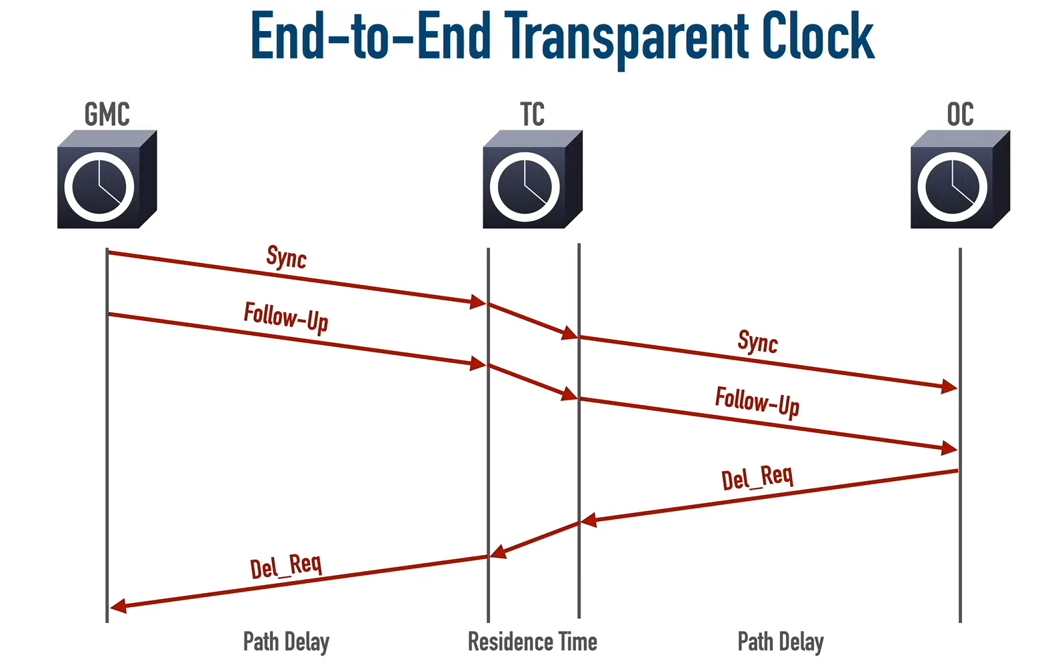
E2E TC
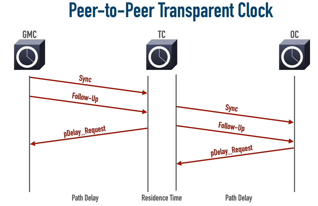
P2P TC
The P2P mechanism is more suitable for mesh networking and allows for fast switching when a link fails, because the latency of each segment is calculated independently; E2E is suitable for chain networking and is more versatile because it allows the network to have ordinary switches (which do not support PTP).
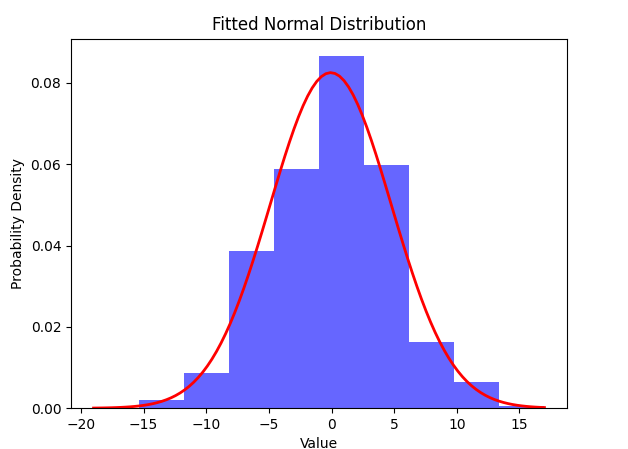
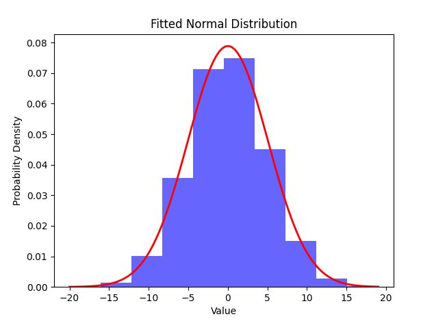
Test result of PTP-optimized SONiC Switches: Within 20ns
By utilizing hardware acceleration and software algorithm optimization, the synchronization accuracy of Asterfusion PTP-optimized switches is distributed within 20ns (CX308P-48Y-N-V2), and the deviation results obtained from different delay measurement modes are almost the same.
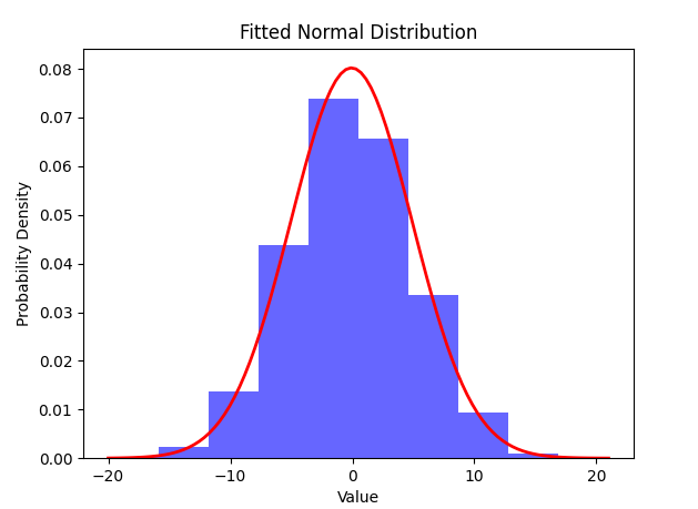
Test1: E2E+onsStep
Test3: E2E+oneStep+syncE
Test2: E2E+twoStep
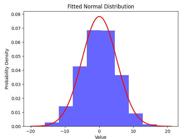
Test4: P2P+twoStep
Asterfusion PTP-optimized Switch Models Powered by Enterprise SONiC
These 12 models support PTP Class C:
-
 16-Port 25G Aggregation Switch 4 Port 100G Uplink Enterprise SONiC Ready
 -
 48-Port 25G 8-Port 100G Uplink Enterprise SONiC Ready
 -
 32-Port 100G QSFP28 Core Switch Enterprise SONiC Ready
 -
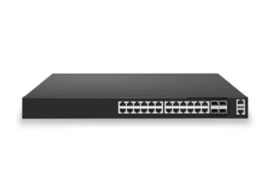 24x1G RJ45 POE+ @740W L3 Access Switch, 4x25Gb SFP28/10Gb SFP+ Uplinks, Enterprise SONiC Ready
 -
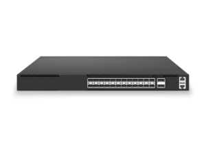 24x25G SFP28, 2x100G QSFP28 Uplinks, L3 Core/Leaf Switch, Enterprise SONiC Ready
 -
 48x1G RJ45 POE+@740W L3 Access Switch, 6x25Gb SFP28/10Gb SFP+ Uplinks, Enterprise SONiC Ready
 -
24x1G RJ45 POE+@370W L3 Access Switch, 4x25Gb/10Gb SFP28 Uplinks, Enterprise SONiC Ready
-
24x1G RJ45 L2/3 Access Switch, 4x25Gb/10Gb SFP28 Uplinks, Enterprise SONiC Ready
-
48x1G RJ45 L2/3 Access Switch, 6x25Gb/10Gb SFP28 Uplinks, Enterprise SONiC Ready
-
48x1G RJ45 POE+@1440W L3 Access Switch, 6x25Gb/10Gb SFP28 Uplinks, Enterprise SONiC Ready
-
 48-Port 25G TOR Data Center Switch SONiC Enterprise Ready
 -
 32-Port 100G QSFP28 Low Latency Data Center Switch, Enterprise SONiC Ready
These 5 models support PTP Class A:
-
 8x 2.5G RJ45 PoE++ L2/3 Access Switch, 2x10Gb SFP+ Uplinks, Enterprise SONiC Ready
 -
8×2.5G RJ45 L2/3 Access Switch, 2x10Gb SFP+ Uplinks, Enterprise SONiC Ready
-
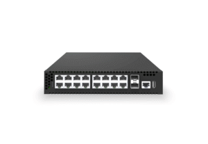 Enterprise SONiC 16 Port Gigabit Switch with Two Marvell OCTEON TX2 CN9130 DPUs as Gateway and Server
 -
8x1G RJ45 POE++ @150W L2/3 Access Switch, 2x10Gb SFP+ Uplinks, Enterprise SONiC Ready
-
16x1G RJ45 POE+@150W L2/3 Access Switch, 2x10Gb SFP+ Uplinks, Enterprise SONiC
| Asterfsuion PTP Feature List – update on 2024.04 | ||||
| PTP | Global view | ptp profile | smpte-2059-2 | |
| 1588v2 | ||||
| clock type | BC | |||
| OC | ||||
| TC | ||||
| PTP Domain | ||||
| PTP enable | ||||
| delay mode | E2E | |||
| P2P | ||||
| step mode | one-step | |||
| two-step | ||||
| clock param | clock-accuracy | |||
| clock-class | ||||
| priority1 | ||||
| priority2 | ||||
| clock-id | ||||
| Trasport mode | UDP_IPv4 | |||
| UDP_IPv6 | ||||
| Port view | PTP enabe | |||
| type | master | |||
| slave | ||||
| auto | ||||
| Announce Message | send interval | |||
| receipt timeout | ||||
| Sync Message | send interval | |||
| Delay/Pdelay Message | send interval | |||
| Display | Global view | grandmaster_clock | id | |
| offset_to_grandmaster | ||||
| path delay | ||||
| servo_state | locked/unlock | |||
| Port view | ptp-status | master | ||
| slave | ||||
Q&A:What do Class A, Class B, and Class C represent In PTP Time Synchronization ITU Classification?

In telecom networks, especially in 5G and future networks, the accuracy of time synchronization is crucial. The ITU (International Telecommunication Union) has classified the time synchronization capabilities of Telecom Boundary Clocks (T-BC) and Telecom Transparent Clocks (T-TC) in the G.8273.2 and G.8273.3 standards, defining Class A, Class B, and Class C to measure the Time Error (TE) performance of devices.
Class C: Time Error ≤ 10 ns, primarily used in scenarios with extremely high synchronization accuracy requirements, such as 5G fronthaul.
Class A: Time Error ≤ 50 ns, suitable for general telecom networks with relatively lower synchronization accuracy requirements.
Class B: Time Error ≤ 20 ns, applicable for more stringent time synchronization scenarios, such as 5G base station synchronization.


